background image

PCAN-TJA1054 - User Manual 

Tip:

 You can find additional information about the properties 

and the behavior of the LS-CAN transceiver TJA1054 in the 

corresponding data sheet, which you can download from the 
web site of Philips (

http://www.semiconductors.philips.com

). 


1.1


System Requirements 

The following prerequisites must be given, so that the PCAN-

TJA1054 can be used properly: 


HS-CAN component capable of routing a 5-Volt supply 

(minimum 80 mA) to the CAN connector (can be set for all 
PC/CAN adapters from the PCAN series) 


1.2


Scope of Supply 

The scope of supply normally consists of the following parts: 


Manual in printed form 


Bus converter PCAN-TJA1054 in small Sub-D adapter case 


Summary of Contents for PCAN-TJA1054

Page 1: ...PCAN TJA1054 Converter High speed CAN Low speed CAN User Manual...

Page 2: ...tions in the text Updated technical specifications All product names mentioned herein may be the trademarks or registered trademarks of their respective companies Furthermore and are not mentioned in...

Page 3: ...ply 5 2 Installation 6 2 1 Connecting the High speed CAN Side 6 2 2 Connecting the Low speed CAN Side 7 3 Application Notes 8 3 1 Transfer Rate 8 3 2 Low power Modes 8 3 3 Red Error LED 9 4 Frequently...

Page 4: ...w speed CAN LS CAN The LS CAN is primarily intended for low speed applications up to 125 kBaud in passenger cars Like the High speed CAN HS CAN the LS CAN transmits signals differentially through two...

Page 5: ...nductors philips com 1 1 System Requirements The following prerequisites must be given so that the PCAN TJA1054 can be used properly HS CAN component capable of routing a 5 Volt supply minimum 80 mA t...

Page 6: ...he PCAN TJA1054 Otherwise the PCAN TJA1054 or the hardware connected may be damaged or destroyed Between CAN_L and CAN_H a terminating resistor of 60 is installed internally Therefore an additional li...

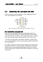
Page 7: ...terminated with 100 parallel connection of all terminating resistors A single node should be terminated with at least 500 and at most 6 k To simplify the adaptation of the PCAN TJA1054 to existing CAN...

Page 8: ...ted to further hardware controllers for example only through the CAN bus it is not capable of activating one of the low power modes If the PCAN TJA1054 shall be connected to the LS CAN bus of a motor...

Page 9: ...ED indicates the state of the error output of the LS CAN transceiver This output is active for the following error conditions on the Low speed CAN side Interrupt on CAN_H Interrupt on CAN_L Short circ...

Page 10: ...r Not at all The PCAN TJA1054 doesn t convert the incoming data with regard to timing Because of this it doesn t have direct influence on the transfer rate This is determined by the nodes of the conne...

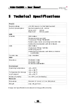
Page 11: ...ination with 62 fixed CAN ISO 11898 3 Transceiver Philips TJA1054 Sub D plug 9 pins Internal bus termination with 560 or 5 66 k switchable Transfer rate max 125 kBit s EMC Directives EN 50081 1 1992 E...

Page 12: ...PCAN TJA1054 User Manual Appendix A Certificates A 1 CE 12...

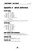
Page 13: ...turned off LS CAN plug Slide switch LS CAN termination 560 for building smaller networks testing single components 5 66 k for monitoring or configuring existing networks already optimum termination I...

Reviews: