


7
Instalación Marina
AVISO
Las instalaciones mar
inas están sujetas a
más vibr
ación y estr
és en los cables
. Las
instalaciones marinas
requier
en cone
xiones eléctricas r
esistentes al agua con
holgura
en los
cables y alambr
es del apar
ato. Use
el aislamiento
de cable apr
opiado par
a el medio ambiente
.
Instale el Tomacorriente Móvil alejado de la humedad y del agua.
Instale el Tomacorriente Móvil por
encima de la línea de flotación, tan alto como sea posible. El
Tomacorriente Móvil no se deberá instalar
por debajo o cerca de la línea de flotación.
La entrada CC al
Tomacorriente Móvil se tiene que conectar con cables marinos apr
obados, usando
acoples y sujetadores marinos no corr
osivos
.
Conexión a la
Fuente
de Energía
ADVERTENCI
A
PELIGR
O DE FUE
GO
No conecte el
Tomacorr
iente Móvil a un
Vehículo R
ecreativ
o (R
V) o
al sistema de
distribución
CA d
e la casa, a un cir
cuito de carga
CA o donde el conductor
neutro esté conectado al
terminal negativ
o de una fuente de ener
gía CC. El
conectarlo a estos circuitos pod
rá causar
le
daños al
Tomacor
riente Móvil y/o
crear
una chispa.
AVISO
No
lo use en
sistemas eléctricos d
e tierra positiv
a. El
conectar el
Tomacor
riente
Móvil a un
sistema eléctrico de tierr
a positiva d
añará el
Tomacor
riente Móvil. Sólo use
el
Tomacorr
iente Móvil en sistemas eléctr
icos de tierra negativ
a. Si tiene
duda, consulte con
el
distribuidor
de su vehículo
o lea el manual
del propietar
io del vehículo
.
Conexión a una Bater
ía de
12 Voltios
o 12 Voltios CC
con los C
ables Suministr
ados
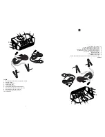
El Tomacorriente Móvil está equipado con dos conector
es de tornillo para sujetar los cables al
Tomacorriente Móvil.
El rojo es positiv
o (+) y el negro es el negativ
o (–).
1.
Seleccione la posición OFF en el
Tomacorriente Móvil.
2.
Remue
va el conector r
oscado positivo (+) r
ojo.
3.
Deslice el cable de batería positivo (+) r
ojo, en el conector r
oscado positivo (+) r
ojo. Instale el
conector roscado r
ojo positivo (+) en el terminal r
ojo positivo (+) y apriete firmemente el conector
.
4.
Remue
va el conector r
oscado negativo (–) negr
o.
5.
Deslice el cable de batería negativo (–) negr
o, en el conector r
oscado negativo (–) negr
o. Instale
el conector roscado negr
o negativo (
–) en el terminal negr
o negativo (
–
) y apriete firmemente el
conector.
6.
Si usa el enchufe de ener
gía de 12 voltios CC
, enchúfelo en un tomacorriente de 12 v
oltios CC y
gírelo liger
amente para asegur
ar una buena conexión.
7.
Si usa los cables de batería suministrados con pinz
as, conecte primer
o la pinza del cable r
ojo
positivo (+) en el terminal (+) de la batería y luego la pinz
a del cable negro negativ
o (
–) en el
terminal negativo de la batería.
AVISO
No
conecte el cable de tierr
a al terminal negativ
o (–) de la fuente de energía.
Sólo
conecte este cable
a un punto de tier
ra limpio
en el vehículo
.
Conexión Dir
ecta a la Fuente de Ener
gía
El Tomacorriente Móvil se puede alambr
ar directamente a la fuente de ener
gía CC. Se debe instalar un
fusible de 200 amperios ANL o un disyuntor CC par
a proteger el cir
cuito.
Determinación de la Longitud y C
alibre Apr
opiados
Mida la distancia entre el
Tomacorriente Móvil y la fuente de ener
gía. Vea las ESPE
CIFICACIONES
para obtener el calibr
e del cable que se debe usar. El usar cables e
xcesiv
amente largos o de calibr
e
insuficiente reducirá la ener
gía de la batería. También, el uso de cables inapr
opiados reducirá el
tiempo de operación de la batería.
AVISO
Use
únicamente cables
de cobr
e par
a conectar el
Tomacor
riente Móvil a la
fuente
de energía.
No use cables
de aluminio
. L
os cables de aluminio tienen apr
oximadamente
1/3
más de
resistencia
que los cables
de cobr
e del mismo tamaño
.
AVISO
Use
solamente conectores
de cable del
tamaño apr
opiado par
a conectar
los cables
al Tomacor
riente
Móvil y a
la fuente de energía.
Asegúr
ese de que los conector
es de
los
cables sean
instalados apropiadamente
en los extr
emos de
los cables.
Instalación de los Cables
1.
Seleccione la posición OFF en el Tomacorriente Móvil
.
2.
Instale el fusible de 200 amperios ANL o el dis
yuntor CC en el terminal positivo (+) de la fuente de
energía.
Retir
e el fusible del porta fusible antes de instalar el por
ta fusible o apague el disyuntor
.
Si el porta fusible o el dis
yuntor no pueden ser instalados en el terminal, use un pedazo de
cable corto del calibr
e recomendado par
a conectar el porta fusible o el dis
yuntor en el terminal.
Identifique este cable como el positivo (+).
3.
Asegur
e el otro e
xtremo del por
ta fusible o disyuntor al cable positiv
o (+). Conecte el cable
positivo (+) al terminal positiv
o rojo en el
Tomacorriente Móvil
. Apriete segur
amente el conector de
tornillo.
4.
Conecte el cable negativ
o entre el terminal negativ
o (–) de la fuente de energía y el terminal
negativo negr
o (–) en el Tomacorriente Móvil
. Apriete segur
amente el conector de tornillo.
7
Marine Installation
Marine installations are subject to additional vibration and stress on the cables.
Marine installations require tight, water-resistant electrical connections with slack in both the
cables and appliance wiring. Use the appropriate cable insulation for the environment.
Install the Mobile Power Outlet away from moisture and water. Install the Mobile Power Outlet above
the waterline, as high as possible. The Mobile Power Outlet must not be installed below or near the
waterline.
The Mobile Power Outlet’s DC input must be connected to approved marine wiring using non-corrosive
marine fasteners and fittings.
Connecting to Power Source
FIRE HAZARD
Do not connect the Mobile Power Outlet to RV or household AC distribution wiring, to an AC
load circuit or where the neutral conductor is connected to the negative terminal of a DC
power source. Connecting to these circuits could cause damage to the Mobile Power Outlet
and/or create a spark.
Do not use with positive ground electrical systems. Connecting the Mobile Power
Outlet to a positive ground electrical system will damage the Mobile Power Outlet. Only use
the Mobile Power Outlet on negative ground electrical systems. If in doubt, check with your
vehicle dealer or consult the vehicle’s owner’s manual.
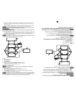
Connecting to 12-volt Battery or 12-volt DC Using Supplied Cables
The Mobile Power Outlet is equipped with two screw connectors to attach the cable leads to the Mobile
Power Outlet. The red is positive (+) and the black is negative (-).
1.
Select the OFF position on the Mobile Power Outlet.
2.
Remove the red positive (+) screw connector.
3.
Slide the red positive (+) cable lead onto the red positive (+) screw connector. Install the red
positive (+) screw connector into the red positive (+) terminal and tighten the screw connector
securely.
4.
Remove the black negative (-) screw connector.
5.
Slide the black negative (-) cable lead onto the black negative (-) screw connector. Install the black
negative (-) screw connector into the black negative (-) terminal and tighten the screw connector
securely.
6.
If using the 12-volt DC power plug, plug the 12-volt DC power plug in a 12-volt DC power socket
and twist slightly to ensure a good connection.
7.
If using the supplied battery cables with clamps, first clamp the red positive (+) clamp onto the
positive (+) terminal of the battery and then the black negative (-) clamp to the negative (-) terminal
of the battery.
Do not connect the grounding wire to the negative (-) terminal of the power source.
Only connect this wire to a clean grounding point on the vehicle.
Hard-Wire to Power Source
The Mobile Power Outlet can be hard-wired to the DC power source. A 200-amp ANL fuse or DC circuit
breaker should be installed to protect the circuit.
Determining Proper Cable Length and Gauge
Measure the distance between the Mobile Power Outlet and the power source. See SPECIFICATIONS
for the proper cable gauge to use. Using excessively long or insufficient gauge cables will cause low
battery power. Also, using improper cables will reduce battery operation time.
Only use copper cables to connect the Mobile Power Outlet to the power source.
Do not use aluminum cables. Aluminum cables have approximately 1/3 more resistance than
copper cables of the same size.
Only use proper size cable connectors to connect the cables to the Mobile Power
Outlet and power source. Be sure the cable connectors are properly installed onto the ends of
the cables.
Installing Cables
1.
Select the OFF position on the
Mobile Power Outlet.
2.
Install the 200-amp ANL fuse or DC circuit breaker onto the positive (+) terminal of the power
source. Remove the fuse from the fuse holder before installing the fuse holder or turn off the
circuit breaker. If the fuse holder or circuit breaker cannot be installed onto the terminal, use a
short length of the recommended cable gauge to connect the fuse holder or circuit breaker to the
terminal. Identify this cable as positive (+).


