6 Installation and start-up
19
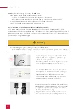
Now connect the 15-20 V side.
▪
Disconnect the pluggable screw terminal (C1,2)
from the Controlpro.
▪
Connect it to the cable wires of the power supply
unit.
▪
Pay attention to the correct polarity, as
indicated on the power supply unit: red (+) and
black (-).
6.4 Connecting and fastening the panel
Preparation
▪
Place the screws (M5x16) included in the scope of delivery within reach for fixing the panel
within the flush-mounted box.
▪
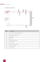
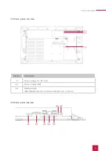
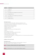
For further notes on the panel‘s ports, please read section 3.8.
Connection of the panel
▪
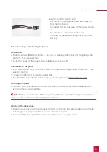
Push the prepared 15-20 V connector terminals back into the appropriate connectors in the
panel (C1 and C2).
▪
Connect the Ethernet cable to the panel (D4).
▪
Plug the KNX cable with the colors red (+) and black (-) into the KNX-terminal “1” (C3).
Mounting the panel
▪
Install the panel into the flush-mounted box. Use the four counter-sunk screws (M5x16) for
fixing it in the flush-mouted box.
Note:
Make sure that the ventilation openings (B5) are not partially or fully covered to ensu-
re convection ventilation of the computer in the panel.
Attaching the glass cover
▪
Place the glass cover with the magnetic holders into the four intakes provided and continue
until the glass rests against all four corners of the touchscreen.
▪
Ensure that the opening for the camera is positioned on the upper screen.
Summary of Contents for Controlpro PNX11-20001
Page 1: ...V 2 1 1 Controlpro User manual EN...
Page 27: ...Declaration of conformity 27...
Page 28: ...www peaknx com...


