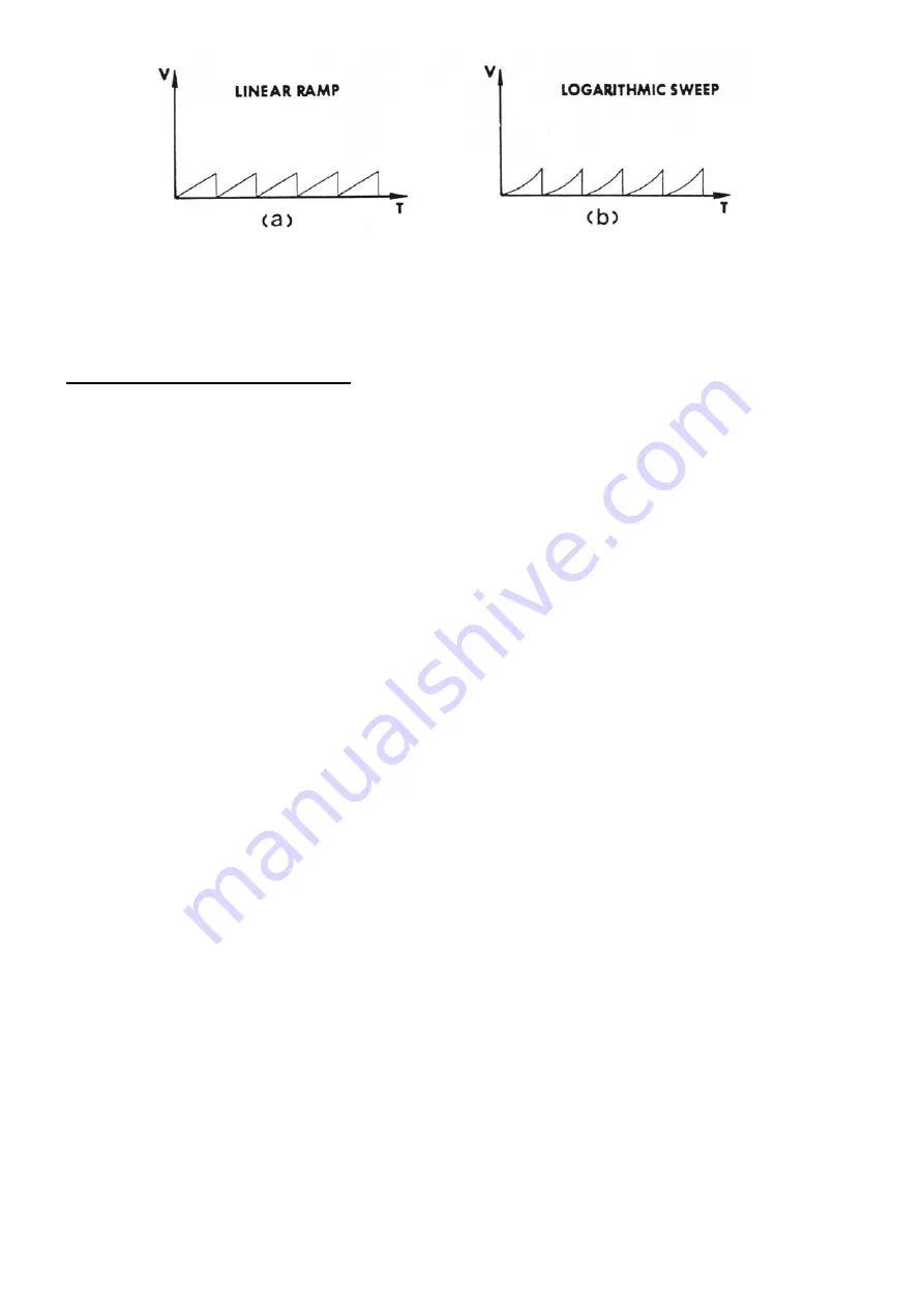
Figure E: Sweep outputs: linear & logarithmic
DC Offset
The DC offset enables varying the DC level of a signal. The signal peak plus the DC offset should not exceed ± 10
Volts (± 5 V into 50
Ω
), otherwise the output waveform will be clipped.
3.4
Frequency Counter Operations
The autoranging frequency counter offered on the PeakTech Generators is one of the most simple and powerful in
existence. Frequencies from 5 Hz to 100 MHz, or periods from 0.2 sec. to 10 nsec max accurately be measured
with a resolution of 6 ½ digits. The PeakTech Generators also may measure the period of the wave by utilizing the
reciprocal counting technique. Thus, providing a means to measure small frequency inputs. Input sensitivity is at 50
mV
rms
to 50 MHz, and 100 mV
rms
to 100 MHz, with a maximum input of 250 V. Furthermore, input waves may be
attenuated at x1 or x20.
To enable the frequency counter mode:
1.
Press the "Ext Freq" key.
2.
If one chooses to measure the period of the wave, press the "Freq/Per" key and "PER" is displayed
on the LCD.
3.
Input the frequency through the "Ext Freq In" BNC Connector.
4.
Read the frequency from the LCD display.
Varying the Frequency Counter parameters
In the Frequency Measurement mode, there are two parameters which may be varied. These two parameters are:
Attenuation and Low Pass Filter. Pressing the "EXT FREQ" key enables the "cursor" to switch between the "low
pass filter" and "attenuation". To vary either of these two parameters, perform the following:
Upon entering the frequency counter mode, one will notice that the low pass filter is "ON", the attenuation is set to
20 dBm and the cursor is set on the attenuation. Attenuation is set at either x1 or x20 and may be varied between
x1 and x20 by adjusting the amplitude knob.
To set the Low Pass Filter "ON" or "OFF", one, press the "EXT FUNC" key so that the cursor is set to "LPF". Two,
press either scroll key to set the Low Pass Filter "on" or "off".
Note:
1.
If a measured signal's frequency is below 20 MHz, set the low pass filter (LPF) on. This provides
a more stable measurement.
2.
If a measured signal's level is too high (> 1 V
rms
), it will cause the electronic circuit to enter
saturation. Therefore, attenuate the signal by x20.
3.
Simultaneous operation of the frequency counter and function generator causes radiation interference
between signals at high frequencies. Do not operate the function generator above 6 MHz when the
frequency counter is measuring signals above 80 MHz.
- 25 -


