background image

4. Precautions for using the power supply 


Caution ! Before connecting the mains plugs of the power supply to the main outlet 
and switching on the equipment, be sure that the correct main voltage is available 
and polarity has been correctly observed. Incorrect polarity can damage the power 
supply and/or any connected equipment. Replace defective fuse only by an 
equivalent type. Before inserting the mains plug in the power outlet ensure that the 
line voltage corresponds with the selected line voltage of the power supplies. 
 
Caution! Never use the instrument without fully closed housing.


4.1. Adjustment of output current (DC) 

 
Caution! Before connecting this power supply to the load ensure that 
the specified maximum output current is not exceeded. 
 
1.  Disconnect the leads from the plus (+) and minus (-) terminals or the AC     

terminals of the power supply. 

2.  Adjust the desired output voltage with the voltage control. 
3.  Turn the current control counter-clockwise. 
4.  Short-circuit the plus and minus output terminals with a suitable short-circuit 

bridge or cable (the bridge or cable must be adequately dimensioned for the 
desired output current).  

Caution! Only possible in DC-voltage range. Short-circuit at AC-voltage 
range activates input-fuse. 

5.  Turn the current control clockwise until the desired current is indicated. 
6.  Remove the short-circuit bridge or cable from the plus and minus terminals. 
7.  The power supply is ready for operation now. 
  

4.2. Operating method


1.  To adjust the desired output voltage (0…30V), first should rotate clockwise the  
 

adjustment knob (12) to maximum, then turn on power switch (1). 

2.  Adjust adjustment knob (14) till output voltage reach required voltage value. 
3.  The LED for constant current (CC) expires and the LED for constant voltage  
 

(CV) lights up. 


-11- 

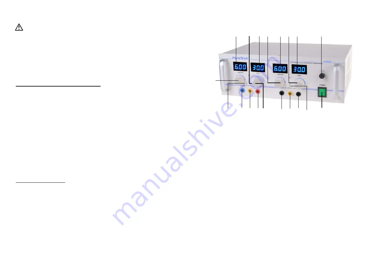
  3. Bedienelemente 


1. Ein/Aus-Schalter 
2. Netzsicherung 

(4A) 

3. Gleichspannungsausgang 

(-) 

4.  Eingangsbuchse für Massepotenzial 
5. Gleichspannungsausgang 

(+) 

6. Wechselspannungsausgang 
7.  Eingangsbuchse für Massepotenzial 
8. Wechselspannungsausgang 
9.  Konstantstrom-Anzeige des DC-Ausgangs (CC) 
10. Konstantspannungsanzeige des DC-Ausgangs (CV) 
11.  Überstromanzeige des AC-Ausgangs (OV) 
12.  Stromregler für DC-Ausgang (Einsteller für Strombegrenzung DC) 
13.  LED-Stromanzeige für DC-Ausgang 
14. Spannungsregler für DC-Ausgang 
15.  LED-Spannungsanzeige für DC-Ausgang 
16.  Stromregler für AC-Ausgang (Einsteller für Strombegrenzung AC) 
17.  LED-Stromanzeige für AC-Ausgang 
18.  Spannungsregler für AC-Ausgang 
19.  LED-Spannungsanzeige für AC-Ausgang 


-4- 


12

3 4 5 

7 8 

19

13

10

15 16

17  18

11

9

14 

Summary of Contents for 5995

Page 1: ... equipment The measurement instrument is not to be to operated unattended Do not subject the equipment to direct sunlight or extreme temperatures humidity or dampness Do not subject the equipment to shocks or strong vibrations Do not operate the equipment near strong magnetic fields motors transformers etc Keep hot soldering irons or guns away from the equipment Allow the equipment to stabilize at...

Page 2: ... bei Kurzschluss dennoch ein gewisser Leistungsabfall stattfindet sollte das Gerät ausgeschaltet und der Fehler gesucht und baldmöglichst beseitigt werden Nach Abschluss des Messbetriebes Gerät ausschalten und in einem trockenen Raum mit ausreichender Belüftung abstellen und lagern Bei längerem Nichtgebrauch des Gerätes Netzstecker aus der Steckdose ziehen Vor Ausführung von Wartungsarbeiten Gerät...

Page 3: ...usganges 1 Zur Einstellung der gewünschten Ausgangsspannung 0 30 V Ampere Regler 12 auf Rechtsanschlag drehen und Gerät mit der Ein Aus Taste 1 einschalten 2 Gewünschte Ausgangsspannung am Ausgang mit den Spannungsregler 14 einstellen 3 Die Konstantstromanzeige CC erlischt und die Konstantspannungs anzeige CV leuchtet auf 5 3 Front Panel Controls 1 Power switch the LED illuminates when the power i...

Page 4: ...DC voltage range Short circuit at AC voltage range activates input fuse 5 Turn the current control clockwise until the desired current is indicated 6 Remove the short circuit bridge or cable from the plus and minus terminals 7 The power supply is ready for operation now 4 2 Operating method 1 To adjust the desired output voltage 0 30V first should rotate clockwise the adjustment knob 12 to maximum...

Page 5: ...cause any damage to the unit But there is still power loss when short circuit in order to reduce aging and energy consumption so this situation should be find as soon as possible and turn off power then exclude the faults When operating is finished put it in a dry place of good ventilation and keep it clean If it is not in use for a long period pull off the power supply plug for storage For mainte...

Page 6: ...tel Benutzen Sie keine ätzenden Scheuermittel Dieses Gerät ist ausschließlich für Innenanwendungen geeignet Vermeiden Sie jegliche Nähe zu explosiven und entflammbaren Stoffen Öffnen des Gerätes und Wartungs und Reparaturarbeiten dürfen nur von qualifizierten Service Technikern durchgeführt werden Gerät nicht mit der Vorderseite auf die Werkbank oder Arbeitsfläche legen um Beschädigung der Bediene...

Page 7: ...us im Inneren des Gerätes Keine metallenen Gegenstände durch die Ventilationsschlitze stecken Keine Flüssigkeiten auf dem Gerät abstellen Kurzschlussgefahr beim Umkippen des Gerätes Gerät nicht in der Nähe starker magnetischer Felder Motoren Transformatoren usw betreiben maximal zulässige Eingangswerte unter keinen Umständen überschreiten schwere Verletzungsgefahr und oder Zerstörung des Gerätes N...

Page 8: ...PeakTech 5995 Bedienungsanleitung operation manual Digitales AC DC Labornetzgerät Digital AC DC power supply ...

Reviews: