background image

3. Operation 


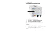
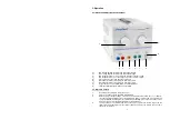
3.1. Controls and description of front-panel 


1.) 

DC voltage adjustment: adjusting DC output voltage 

2.) 

AC voltage adjustment: adjusting AC output voltage  

3.) 

DC output terminal (-): connecting the negative terminal of load  

4.) 

DC output terminal (+): connecting the positive terminal of load 

5.) 

Case ground: connecting the case to ground  

6.) 

AC output terminal: connecting the terminal of load  

7.) 

AC output terminal: connecting the terminal of load 

8.) 

Power switch: the unit is ON when the LED illuminates 

9.) 

LED: the LED illuminates when the unit in ON 


3.2. Operation method 
 

1. 

Insert AC power plug into AC power outlet. 

2. 

Turn on the power switch, the LED will illuminate. 

3. 

With the proper output voltage, connect the unit with terminal of AC (6), (7) or DC (3), 

(4) to the equipment. Make sure your equipment’s power cord must be connected to the 

correct polarity (DC output), which is marked near binding post on the front panel of the 

unit. The reversal of polarity may damage your equipment. 

4. 

The  Fuse  which  is  located  at  the  rear  of  the  unit  for  protection  the  AC  input  can  be 

replaced by unscrewing fuse holder when it have been burnt out. Please use the same 

rated one for replace. 


-7- 

3. 

2. 

6. 

4. 

5. 

1. 

7. 

8. 

9. 

Summary of Contents for 6125

Page 1: ...PeakTech 6125 6130 Bedienungsanleitung Operation Manual AC DC Labornetzgeräte Power Supplies ...

Page 2: ...herungen nur mit einer dem Originalwert entsprechenden Sicherung ersetzen Sicherung oder Sicherungshalter niemals kurzschließen Gerät Prüfleitungen und sonstiges Zubehör vor Inbetriebnahme auf eventuelle Schäden bzw blanke oder geknickte Kabel und Drähte überprüfen Im Zweifelsfalle keine Messungen vornehmen Messarbeiten nur in trockener Kleidung und vorzugsweise in Gummischuhen bzw auf einer Isoli...

Page 3: ...rie verbindet leichte Bedienbarkeit ein unverwüstliches Gehäuse neuartiges Design und hohe Leistungsstärke mit einem hervorragenden Preis Leistungsverhältnis Durch die außergewöhnlichen Leistungsmerkmale sind diese Netzgeräte hervorragend geeignet für den Einsatz im Forschungs und Entwicklungsbereich in Technischen Hochschulen der Elektroindustrie und für den mobilen Wartungs und Reparaturdienst 2...

Page 4: ...ngsbuchse Verbinden mit der Wechselspannungslast 8 Ein Ausschalter Das Gerät ist eingeschaltet wenn die LED 9 erleuchtet 9 LED die LED dient zur Überwachung des Gerätestatus 3 2 Bedienung 1 Verbinden Sie den Gerätestecker mit einer passenden Steckdose 2 Betätigen Sie den Ein Ausschalter Die LED wird erleuchten 3 Verbinden Sie nach dem Einstellen der korrekten Ausgangsspannung Ihren Verbraucher Las...

Page 5: ...ielfältigung dieser Anleitung oder Teilen daraus vorbehalten Reproduktionen jeder Art Fotokopie Mikrofilm oder ein anderes Verfahren nur mit schriftlicher Genehmigung des Herausgebers gestattet Letzter Stand bei Drucklegung Technische Änderungen des Gerätes welche dem Fortschritt dienen vorbehalten Hiermit bestätigen wir dass alle Geräte die in unseren Unterlagen genannten Spezifikationen erfüllen...

Page 6: ...t to shocks or strong vibrations Do not operate the equipment near strong magnetic fields motors transformers etc Keep hot soldering irons or guns away from the equipment Allow the equipment to stabilize at room temperature before taking up measurement important for exact measurements Use caution when working with voltages above 35V DC or 25V AC These Voltages pose shock hazard Periodically wipe t...

Page 7: ...ectronic appliance maintenance and etc 2 1 Technical Data Input voltage 110 V AC 127 V AC 10 60 Hz 220 V AC 240 V AC 10 50 Hz switchable Output voltage 1 V 2 V 3 V 4 V 5 V 6 V 7 V 8 V 9 V 10 V 11 V 12 V 13 V 14 V 15 V Output current 5 A P 6125 10 A P 6130 DC line regulation 1 DC load regulation 1 DC ripple voltage 1mV Protection over current over temperature dimensions WxHxD 170 x 166 x 286 mm wei...

Page 8: ...ates 9 LED the LED illuminates when the unit in ON 3 2 Operation method 1 Insert AC power plug into AC power outlet 2 Turn on the power switch the LED will illuminate 3 With the proper output voltage connect the unit with terminal of AC 6 7 or DC 3 4 to the equipment Make sure your equipment s power cord must be connected to the correct polarity DC output which is marked near binding post on the f...

Page 9: ...nowing Technical changings which are in the interest of progress reserved We herewith confirm that the units are calibrated by the factory according to the specifications as per the technical specifications We recommend to calibrate the unit again after 1 year PeakTech 031 2 0163 Sch Th pt PeakTech Prüf und Messtechnik GmbH Gerstenstieg 4 DE 22926 Ahrensburg Germany 49 0 4102 42343 44 49 0 4102 43...

Reviews: