background image

5. Operating method 


1.  Setting the constant voltage output: 

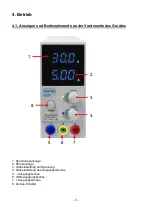
Turn the current regulator (4) clockwise until it stops. Turn on the machine's power switch 
(8) and turn the voltage regulator (3) to the desired output voltage. 


2.  Current limitation / constant current output: 

Disconnect  a  possible  connected  load  from  the  output  sockets.  Turn  on  the  power  switch 
(8)  and  adjust  the  voltage  regulator  (3)  clockwise  to  the  desired  output  voltage.  Turn  the 
current regulator (4) counter-clockwise until it stops.  
Short the output sockets (5 + 7) of the power supply by means of a shorting bridge and then 
turn  the  current  regulator  (4)  clockwise  to  set  the  desired  output  current  respectively  the 
desired current limit. 


Note:  

The  maximum  output  current  is  determined  by  the  connected  load.  You  can

’t  charge  a 

connected  consumer  with  a  higher  power  than  it  actually  needs.  To  achieve  the  full  5A, 
short the output sockets for adjusting the current limitation.


6. Caution ! 

 
1. 

If  the  power  supply  cannot  be  turned  on  and  the  mains  supply  is turned  on,  the  fuse  of the 


laboratory  power  supply  maybe  triggered.  Turn  on  the  laboratory  power  supply,  unplug  the 


power cord and replace the fuse.   


Does the replacement of the fuse is not successful, maybe a defective in the device can be 
present. 


Consult your dealer to carry out an inspection. 

 
2. 

If  the  output  voltage  in  constant  voltage  mode  is  lower  than  the  preset  voltage  and  the  CC 
indicator  lights,  the  power  supply  has  automatically  switched  to  the  constant  current  mode. 
Check the connected load or increase the output current. 

 
3. 

If  the  output  current  in  constant  current  mode  is  lower  than  the  preset  current  and  the  CV 


indicator  lights,  the  power  supply  has  automatically  switched  to  the  constant  voltage  mode.


Check the connected load or increase the output voltage. 


4.   If  the  output  voltage  in  constant  voltage  operation  is  not  stable  or  jumps,  it  is  probably  the 

mains supply voltage drops below 90% of the rated value. If the problem is not caused by the 
mains supply voltage, contact your dealer. 


7. Caution ! 

 
In  the  event  of  a  short  circuit  at  the  output  the  current  will  limit  at  the  value  set  by  the  current 
controls, however the unit should be turned off and the short circuit removed before continuing use.  
 
The  mains  power  must  be  switched  off  before  servicing  and  servicing  should  be  referred  to  a 
qualified  person. The  unit should be  stored  in a  dry  and  well  ventilated  place  and  the  power  cord 
removed if storing for long periods.  
 
Laboratory Power Supplies are not designed for charging batteries. Any use of this type can cause 
serious damage to the device, which are exempt from any legal claims whatever. 


- 9 - 

Summary of Contents for 6225

Page 1: ...PeakTech 6225 Bedienungsanleitung Operation Manual Labor Schaltnetzgerät Laboratory Switching Mode Power Supply ...

Page 2: ...en Gerät keinen extremen Temperaturen direkter Sonneneinstrahlung extremer Luftfeuchtigkeit oder Nässe aussetzen Starke Erschütterung vermeiden Gerät nicht in der Nähe starker magnetischer Felder Motoren Transformatoren usw betreiben Heiße Lötpistolen aus der unmittelbaren Nähe des Gerätes fernhalten Vor Aufnahme des Messbetriebes sollte das Gerät auf die Umgebungstemperatur stabilisiert sein wich...

Page 3: ...echnische Daten Spannungsversorgung 200 240 V AC 50 60 Hz umschaltbar extern Ausgangsspannung 1 30 V DC Ausgangsstrom 0 5 A DC Netzstabilität CV 20 mV CC 20 mA 0 100 Last Laststabilität CV 50 mV CC 20 mA 0 100 Last Restwelligkeit CV 50 mV CC 20 mA 0 100 Last Überlastschutz Strombegrenzerschaltung und kurzschlussfest Genauigkeit Spannungsanzeige 0 5 2 Stellen Stromanzeige 0 5 2 Stellen Abmessungen ...

Page 4: ...nelemente an der Vorderseite des Gerätes 1 Spannungsanzeige 2 Stromanzeige 3 Grobeinstellung der Spannung 4 Grobeinstellung des Ausgangsstromes 5 Ausgangsbuchse 6 GND Ausgangsbuchse 7 Ausgangsbuchse 8 An Aus Schalter 3 1 2 3 4 7 6 5 8 ...

Page 5: ...er tatsächlich benötigt 6 Achtung 1 Wenn die Stromversorgung nicht eingeschaltet werden kann und die Netzversorgung ist eingeschaltet kann die Sicherung des Labornetzgerätes ausgelöst haben Schalten Sie das Labornetzgerät aus ziehen Sie das Netzkabel ab und wechseln Sie die Sicherung Führt der sicherungswechsel nicht zum Erfolg kann ein Defekt des Gerätes vorliegen Wenden Sie sich in diesem Fall a...

Page 6: ...erien konzipiert Eine solche Benutzung kann zu schwerwiegenden Beschädigungen am Gerät führen welche von Ansprüchen jeglicher Art ausgeschlossen sind Alle Rechte auch die der Übersetzung des Nachdruckes und der Vervielfältigung dieser Anleitung oder Teilen daraus vorbehalten Reproduktionen jeder Art Fotokopie Mikrofilm oder ein anderes Verfahren nur mit schriftlicher Genehmigung des Herausgebers g...

Page 7: ...bes for faulty insulation or bare wires before connection to the equipment To avoid electric shock do not operate this product in wet or damp conditions Conduct measuring works only in dry clothing and rubber shoes i e on isolating mats Never touch the tips of the test leads or probe Comply with the warning labels and other info on the equipment The measurement instrument is not to be to operated ...

Page 8: ...enables the user to read the fixed values very fast precise and the outputs for constant voltage and current are continuously adjustable 3 Technical Data Operation voltage 200 240 V AC 50 60 Hz switchable extern Output voltage 1 30 V DC Output current 0 5 A DC Line regulation CV 20 mV CC 20 mA 0 100 Load Load regulation CV 50 mV CC 20 mA 0 100 Load Ripple and noise CV 50 mV CC 20 mA 0 100 Load Pro...

Page 9: ...tion of front panel 1 Voltage indication 2 Current indication 3 Coarse adjustment of output voltage 4 Coarse adjustment of current 5 Negative output terminal 6 GND Output 7 Positive output terminal 8 Power ON OFF switch 8 1 2 3 4 7 6 5 8 ...

Page 10: ...ective in the device can be present Consult your dealer to carry out an inspection 2 If the output voltage in constant voltage mode is lower than the preset voltage and the CC indicator lights the power supply has automatically switched to the constant current mode Check the connected load or increase the output current 3 If the output current in constant current mode is lower than the preset curr...

Page 11: ...al knowing Technical changings which are in the interest of progress reserved We herewith confirm that the units are calibrated by the factory according to the specifications as per the technical specifications We recommend to calibrate the unit again after one year PeakTech 11 2014 Pt PeakTech Prüf und Messtechnik GmbH Kornkamp 32 DE 22926 Ahrensburg Germany 49 0 4102 42343 44 49 0 4102 434 16 in...

Reviews: