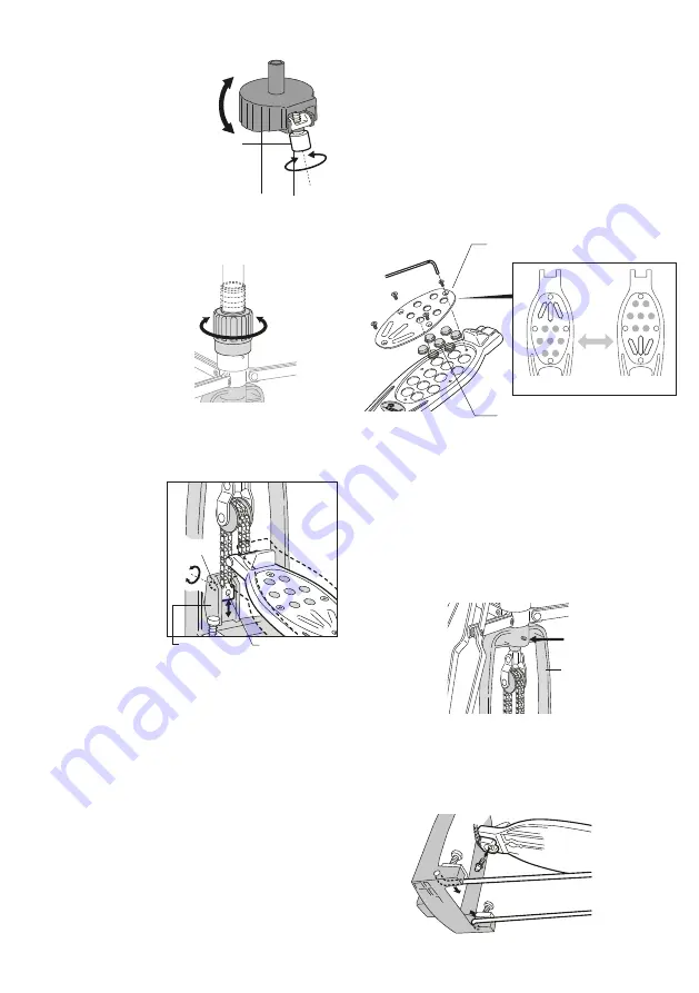
Hi-hat Cup Tilt Adjustment
Turn the Knurled Knob to tilt the
bottom cymbal to help prevent "air
lock" between the cymbals (Fig. 5).
Fig. 5
Knurled Knob
Footboard Angle Adjustment
To change the footboard
angle, loosen the Key
Bolt and slide the Chain
End Connector up or
down until the desired
angle is achieved. Make
sure that the Chain End
Connector is securely
engaged with the teeth in
the Casting before
tightening the Key Bolt.
(Fig. 7).
Casting
Chain End
Connector
Fig. 7
Strong
Light
Spring Tension Adjustment
The spring tension can
be adjusted quickly and
precisely by turning the
Spring Tension Dial. This
innovative system
features extended
tension range and
click-stops for slip-proof
performance under the
most demanding playing
conditions (Fig. 6).
Fig. 6
Key Bolt
Fig. 8-A
Traction Plate
Traction Grip
TractionPlate / Traction Grips
The Traction Plate is reversible to provide just the right
amount of grip at either the front or rear of the footboard.
The Traction Grip dots can be removed as needed to
custom tailor the amount of traction for your personal
playing style. For either adjustment, remove the four Allen
screws holding the Traction Plate with the included Allen
Wrench (Fig. 8-A). The Traction Plate can then be reversed
(Fig. 8-B), the Traction Grip dots removed and rearranged,
or both. Note: When reattaching the Traction Plate,
finger-tighten the four screws to prevent cross-threading
then tighten the screws securely.
To protect the chain from damage when transporting your
H-1000K it is advisable to remove the chain from the
footboard. To remove the chain, remove the Key Bolt as
shown in (Fig.10.) After removing the chain, thread the Key
Bolt finger tight back into the footboard for safe keeping until
the chain is reattached.
<
CAUTION
>
1) To prevent damage to the footboard, periodically inspect the screws
on the TractionPlate to ensure that they are tight and evenly tensioned.
An Allen wrench is provided for this purpose.
2) Always use the pedal with the Traction Plate mounted to prevent
possible injury to your foot.
Maintenance
The Base Tube is secured to the Support Casting with an Allen
screw. In the event the Base Tube becomes loose, tighten the
Allen screw with the provided Allen wrench to restore stability
(Fig. 9).
Allen Screw
Fig. 9
Fig. 10
Support Casting
Fig. 8-B


