Rear Panel
1
2
3
4
5
6
7
8
9
DESIGNED AND ENGINEERED IN U.S.A.
REFER ALL SERVICING TO PEAVEY
AUTHORIZED SERVICE CENTER
CAUTION
ALL TUBES 12AX7A
6505
EFFECTS
PREAMP
A PRODUCT OF PEAVEY ELECTRONICS CORP.
5022 HARTLEY PEAVEY DRIVE
MERIDIAN MS. 39305, U.S.A.
SEND
BIAS
TEST
FUSE
100V
F8AL/250V
115V
F5AL/250V
220/240V
F3.15AL/250V
100-240V
50/60Hz
400 WATTS
Consumo de energia 400Wh
Consumo de energia
en modo de espera 71Wh
BIAS
VOLTAGE
GND
RETURN
OUT
REMOTE SWITCH
Made in China
CLASS 2 WIRING
SPEAKER OUTPUTS
120W RMS/44V RMS 4
Ω
MIN.
SPEAKER JACKS PARALLELED
100V
100
V
240V
240V
0
1
2
3
4
5
6
7
8
9
10
0
1
2
3
4
5
6
7
8
9
10
0
1
2
3
4
5
6
7
8
9
10
0
1
2
3
4
5
6
7
8
9
10
0
1
2
3
4
5
6
7
8
9
10
0
1
2
3
4
5
6
7
8
9
10
0
1
2
3
4
5
6
7
8
9
10
0
1
2
3
4
5
6
7
8
9
10
0
1
2
3
4
5
6
7
8
9
10
0
1
2
3
4
5
6
7
8
9
10
0
1
2
3
4
5
6
7
8
9
10
0
1
2
3
4
5
6
7
8
9
10
0
1
2
3
4
5
6
7
8
9
10
0
1
2
3
4
5
6
7
8
9
10
CHANNEL
BRIGHT
CRUNCH
SELECT
HIGH
MID
LOW
PRE
INPUT
POST
HIGH
MID
LOW
PRE
POST
RESONANCE
PRESENCE
RESONANCE
PRESENCE
POWER
ON
ON
STANDBY
RHYTHM
RHYTHM
LEAD
LEAD
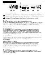
(1) LINE CORD (120 V units only)
For your safety, we have incorporated a 3-wire line (mains) cable with proper grounding facilities. It is
not advisable to remove the ground pin under any circumstances. If it is necessary to use the 6505ii
without proper grounding facilities, suitable grounding adaptors should be used. Greatly reduced
shock hazard exists when the unit is operated with the proper grounded receptacles.
(2) FUSE
WARNING: THE FUSE SHOULD ONLY BE REPLACED WHEN THE POWER CORD
HAS BEEN DISCONNECTED FROM ITS POWER SOURCE. A 5 amp fuse is located within the cap of the fuse
holder. It must be replaced with the same type and value in order to avoid damage to the equipment
and to prevent voiding the warranty. If the amp repeatedly blows fuses, it should be taken to a
qualified service center for repair.
(3) GROUND SWITCH
This is a three-position, rocker type switch which, for most applications, should be operated in
the center (zero) position. If hum or noise is noticed coming from the speaker enclosure(s) with
the Ground Switch in the center position, place the Ground Switch to positive (+) or negative (-)
to minimize hum. Should a hum/noise problem continue, consult your authorized Peavey dealer, the
Peavey factory, or a qualified service technician.
(4) BIAS TEST TERMINAL
These terminals, along with the adjustment knob behind the grill are provided to measure and adjust
the power amp tubes’ bias. The bias adjustment should only be done by a
alified technician.
(5) EFFECTS SEND/EFFECTS RETURN
Signals are supplied to outboard effects or signal processing units by patching from the Effects
Send output into the outboard unit(s) and back into the Effects Return input using shielded
cables with 1/4" mono phone plugs. Only non-gain effects devices (chorus, reverb, delay, etc.)
should be used in the effects loop. If footswitch is used, “Effects” must be selected (LED
illuminated) for effects to work.
(6) PREAMP OUT
This output can be used to send a preamp signal from the 6505 II to a mixing console, tape
recorder, etc., using a shielded instrument cable. Patching from the PREAMP OUT does not affect the
normal operation of the amplifier.


