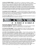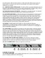
(8) OUTPUT LEVEL: Adjusts the post-processing gain to make up for compression loss. It
does not adjust the input level. The input levels should be set by the source equipment to 0 dBu
(1/4" jacks) or +4 dBu (XLR jacks) for best noise performance. The output level is monitored by an
LED meter to give a visual indication of signal strength.
(9) GAIN REDUCTION METER: A twelve segment LED array that tells how much gain reduction
is being applied to the signal. If this meter is not active, there is no change to the input signal. It is
very useful for making adjustments, since the action of all controls is easily seen.
(10) OUTPUT LEVEL METER: This is a peak indicating meter that is connected to the output jack.
The 0 dB point is 0 dBu for the 1/4" jacks and +4 dBu for the XLR jacks.
(11) EXTERNAL SIDE CHAIN ENABLE: The side chain is actually an alternate loop inserted into
the detector path. This switch enables external processing. Frequency shaping can be applied for
de-essing (add a 2 kHz to 6 kHz bandpass filter) and rumble removal (add a 40 Hz to 120 Hz cut). If
there is nothing plugged into the side chain jack at the back of the unit, it connects the opposite
channel's signal to the detector and uses it for control, making this channel reduce amplitude (or
duck) when a signal is present on the other channel. Adjust the compressor controls for the desired
amount of action. When the side chain is active the LED will illuminate.
(12) BYPASS: This is a hard wired bypass switch that connects the input jack directly to the output
jack (same type only). The 1/4" jacks are connected together and the XLR jacks are connected
together. Bypass will not function for 1/4" input to XLR output or XLR input to 1/4" output. When the
bypass is enabled the LED will illuminate.
(13) STEREO LINK: If the compressor is to be used with stereo signals, the link switch should
be pressed. It sums the RMS detector voltages together for an accurate representation of the two
levels, and locks the channels together to maintain the stereo image during compression. When
the link switch is pressed, all of channel A’s controls except the output level affect both channels.
The controls for channel B are disabled except its output level. As a reminder of this, the gain reduc-
tion meter for channel B is disconnected. The gain reduction meter for channel A is accurate for both
channels and should be used to monitor VCA activity. When the stereo link is enabled the LED will
illuminate
(14) POWER SWITCH: Power is applied when this switch is pressed. As with all devices, the
power to external devices should be applied first, then the mixer and finally the power amp to
minimize turn on transients.
(15) POWER LED Indicates that AC mains power is connected and power switch is in the on
position.
5
Summary of Contents for CEL-2
Page 1: ...O W N E R S M A N U A L CEL 2 2 Channel Compressor Expander Limiter...
Page 28: ...28 NOTES...
Page 29: ...29 NOTES...


