background image

8

S

Se

ettttiin

ng

g  tth

he

e  C

Co

on

nttrro

ollss

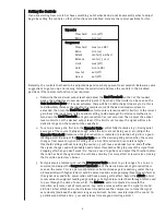
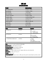
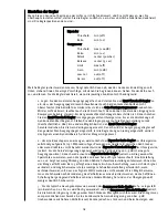
If you are starting from scratch or have something out of whack and do not know exactly what to adjust‚
begin by setting the controls so that all functions are disabled. Here are the control positions for this:

E

Exxp

pa

an

nd

de

err

Threshold

Ratio

C

Co

om

mp

prre

esssso

orr

Threshold

Ratio

Attack

Release

Limit

Gain

Low Cut

De-ess

min (off )

min (1:1)

max (+20 dB)

min (1:1)

center (50 mSec)

center (.5 sec)

max (off )

min (0 dB)

out (off )

out (off )

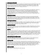
Naturally‚ the controls that need to be adjusted depend on what you want to accomplish. Below are some
suggestions to get you up and running. Follow the order listed and leave the controls in the disabled
positions if that particular function is not required.

1. Determine the maximum output level and adjust the LLiim

miitt  T

Th

hrre

essh

ho

olld

d  so that‚ at the loudest

peaks‚ the output level never exceeds this point. (The action of the limiter can be seen on the
G

Ga

aiin

n  R

Re

ed

du

uccttiio

on

n  M

Me

ette

err. If it never activates‚ there will be no LED activity.) One way to do this is

to deliberately increase the input to the compressor until the desired maximum level is
exceeded‚ then turn the LLiim

miitt  T

Th

hrre

essh

ho

olld

d  control counter-clockwise until it limits it to the correct

gain. Reset the input level to the nominal setting (0 dBu average). An alternate method is to
turn down the LLiim

miitt  T

Th

hrre

essh

ho

olld

d  until gain reduction has just occurred. Then‚ adjust the output

level control to set the desired output level. If the limit is set too low‚ the signal will lose its
dynamic range and the sound will be squashed.

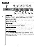
2. To set up a noise gate‚ first turn the E

Exxp

pa

an

nd

de

err  R

Ra

attiio

o  control fully clockwise (1:5). During quiet

passages of the source (between songs‚ when the mics are not being used‚ etc.) adjust the
E

Exxp

pa

an

nd

de

err  T

Th

hrre

essh

ho

olld

d  clockwise until gain reduction is indicated (a reduction of -9 dB is a good

starting point). Re-adjust the E

Exxp

pa

an

nd

de

err  R

Ra

attiio

o  to set the desired gating action when the source

changes from noise to signal. A setting of 1:1.2 has little action and can tolerate higher
threshold settings without coloring the sound; 1:5 will cause an abrupt turn on and off when
the signal changes and will probably need a lower threshold setting to prevent the signal from
dropping off when you don’t want it to. You may need to go back and adjust the threshold after
the ratio has been changed since the soft-knee circuitry has more affect at lower ratios‚ making
the transition point less obvious.

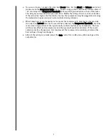
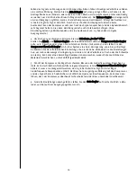
3. For typical voice compression‚ set the C

Co

om

mp

prre

esssso

orr  R

Ra

attiio

o  control to 4:1 (a range of 2:1 to 6:1 is

common) and adjust the C

Co

om

mp

prre

esssso

orr  T

Th

hrre

essh

ho

olld

d  until the desired amount of gain reduction is

seen on the meter. This is a personal preference but continuous gain reduction greater than -9
dB (especially with higher ratios) could be excessive and create pumping/breathing artifacts as
the signal rises and falls. Lower ratios will have a more gentle affect. Adjust the A

Atttta

acck

k  control

to low values to suppress leading-edge spikes or to high values to let them through (often used
to pass through the click of a drum hit). The R

Re

elle

ea

asse

e  control is adjusted to smooth the

transition as it comes out of compression. Too quick a release will cause the signal to sound
artificial. A fast attack and a short release time will cause the compressor to track the signal
very closely (and keep the dynamic range very limited)‚ but can severely impact the sound. (A
50 millisecond attack and a .5 second release time are good starting points.)

Summary of Contents for CEL-2A

Page 1: ...For more information on other great Peavey products go to your local Peavey dealer or online at www peavey com CEL 2A Dual Compressor Expander Limiter Operating Manual ...

Page 2: ...ole est utilisé dans ce manuel pour indiquer à l utilisateur la présence d une tension dangereuse pouvant être d amplitude suffisante pour constituer un risque de choc électrique Ce symbole est utilisé dans ce manuel pour indiquer à l utilisateur qu il ou qu elle trouvera d importantes instructions concernant l utilisation et l entretien de l appareil dans le paragraphe signalé A AT TT TE EN NT TI...

Page 3: ...nufacturer or sold with the apparatus When a cart is used use caution when moving the cart apparatus combination to avoid injury from tip over 14 Unplug this apparatus during lightning storms or when unused for long periods of time 15 Refer all servicing to qualified service personnel Servicing is required when the apparatus has been damaged in any way such as power supply cord or plug is damaged ...

Page 4: ...can be used simultaneously either by themselves or with an external signal applied at the rear jack A dual mono stereo link switch sums the RMS detected signal levels of each channel together to accurately represent the stereo signal s amplitude This voltage is used to control both VCAs In this mode only the controls associated with Channel A function The gain meter of Channel B follows Channel A ...

Page 5: ...e channel s condition When the unit is operating the LED is green processing happening when the LED is red the unit is bypassed 4 4 E Ex xt te er rn na al l S Si id de e c ch ha ai in n E En na ab bl le e The side chain is an insert loop inserted into the detector path so that the signal sent to the detector can be rerouted through an external device or replaced altogether This switch enables the ...

Page 6: ...input changes will not be lost during compression Higher settings smooth out compression effects 1 11 1 L Li im mi it te er r T Th hr re es sh ho ol ld d The limiter is an infinite ratio compressor The threshold control defines the point that absolute limiting begins The limit LED will light when this threshold has been exceeded To disable limiting set this control to maximum 1 12 2 G Ga ai in n A...

Page 7: ...be used to plug into the TRS insert of a mixer The tip is input ring is output which match the insert jack wiring of all current Peavey mixers 2 22 2 2 23 3 2 29 9 3 30 0 B Ba al la an nc ce ed d I In np pu ut ts s XLR and 1 4 TRS balanced inputs for line level inputs Pin 2 tip is the positive phase pin 3 ring is the negative phase If unbalanced inputs are used the negative phase must be grounded ...

Page 8: ...clockwise 1 5 During quiet passages of the source between songs when the mics are not being used etc adjust the E Ex xp pa an nd de er r T Th hr re es sh ho ol ld d clockwise until gain reduction is indicated a reduction of 9 dB is a good starting point Re adjust the E Ex xp pa an nd de er r R Ra at ti io o to set the desired gating action when the source changes from noise to signal A setting of ...

Page 9: ... may be exaggerated causing the material to drop excessively in volume duck during sibilance 5 When heavy bass or low frequency noise causes the compressor to drop levels unnecessarily the side chain L Lo ow w c cu ut t filter can be used When activated the C Co om mp pr re es ss so or r T Th hr re es sh ho ol ld d should be reset since a large portion of the signal usually contains low frequency ...

Page 10: ... 20K oHms XLR Pin 1 ground Pin 2 positive phase Pin 3 negative phase TRS balanced 20K oHms 1 4 Sleeve ground Tip positive phase Ring negative phase 1 4 In Out Phone unbalanced 10K oHms 1 4 phone tip input ring output see control functions above T TH HD D Less than 0 1 20 Hz 20 kHz 10 Hz 80 kHz BW S Si ig gn na al l t to o n no oi is se e 97 dB 0 dBu reference level F Fr re eq qu ue en nc cy y R Re...

Page 11: ...ttings behind the lead vocalist Therefore a ratio from 4 1 up to 6 1 is not uncommon with the threshold set to 10 For the attack a quick response time of 35mS will deliver the smoothness necessary and a release time of 75S will keep the level right at the end of each phrase Expansion gate settings are similar to lead vocalists with a threshold setting of 25 and a ratio of 1 2 dependent on ambient ...

Page 12: ...in a little compression can go a long way If the bass and amp are quiet the expansion can be bypassed but may be brought in as with the electric guitar if necessary Maintaining consistent volume among all the strings is made easier with the CEL 2A Start by setting the downward expander threshold at 35 and the ratio at 1 2 5 The compressor s threshold can be placed at 10 the ratio at 3 1 attack at ...

Page 13: ... aktiviert ist Jede Stufe Expander Kompressor oder Limiter kann so eingestellt werden dass sie durch Schwellen oder Verhältnisjustierung deaktiviert werden kann Ein Sidechain Insert mit eigenem Aktivierungsschalter im Detektorweg ermöglicht Veränderung oder Austausch des Detektorsignals In die Sidechain eingebaut sind zwei wählbare Filter Ein Tiefpassfilter der die Niederfrequenzmodulation vom Det...

Page 14: ...das Gerät umgangen wird Eine zweifarbige Status LED zeigt den Zustand des Kanals an Ist das Gerät in Betrieb leuchtet die LED grün eine Verarbeitung erfolgt wird das Gerät umgangen leuchtet die LED rot 4 4 E Ex xt te er rn na al l S Si id de e c ch ha ai in n E En na ab bl le e Die Sidechain ist eine Insert Schleife die in den Detektorweg eingeschleift wird sodass das an den Detektor gesendete Sig...

Page 15: ... keine Kompression Ein Verhältnis von 2 1 bis 4 1 wird in der Regel für Gesang und Musikinstrumente verwendet Ein hohes Verhältnis liefert eine leicht begrenzende Funktion da der Kompressor mit Soft Knee Topologie arbeitet Zur Deaktivierung der Kompression wird das Verhältnis auf 1 1 eingestellt 9 9 C Co om mp pr re es ss so or r A At tt ta ac ck k Hiermit wird die Geschwindigkeit eingestellt mit ...

Page 16: ...er gedrückt werden So erfolgen eine echte RMS Summierung zur präzisen Darstellung der Pegel von Kanal A und B und deren Verknüpfung sodass der Stereoeindruck während der Bearbeitung gewährleistet bleibt Wird der Link Schalter gedrückt werden die Regler von Kanal A zu Master Reglern die für beide Kanäle gelten Die Regler für Kanal B werden deaktiviert Die Messgeräte von Kanal B zeigen weiterhin die...

Page 17: ...erden kann Die Spitze ist der Eingang der Ring der Ausgang was mit der Verdrahtung der Insert Klinken aller aktuellen Peavey Mischpulte übereinstimmt 2 22 2 2 23 3 2 29 9 3 30 0 B Ba al la an nc ce ed d I In np pu ut ts s Symmetrierte XLR und 1 4 TRS Eingänge für Line Pegeleingänge Pin 2 Spitze ist die positive Phase Pin 3 Ring ist die negative Phase Werden unsymmetrierte Eingänge verwendet muss d...

Page 18: ...Ex xp pa an nd de er r R Ra at ti io o R Re eg gl le er r im Uhrzeigersinn vollständig aufgedreht 1 5 Während ruhiger Passagen der Quelle z B zwischen den Stücken oder wenn die Mikros nicht benutzt werden wird der E Ex xp pa an nd de er r T Th hr re es sh ho ol ld d R Re eg gl le er r im Uhrzeigersinn justiert bis die Gain Verringerung angezeigt wird eine Verringerung von 9 dB ist eine gute Ausgan...

Page 19: ...o R Re eg gl le er r auf 4 1 ein Sprechen oder singen Sie mit starkem Zischen mit vielen s und stellen Sie den C Co om mp pr re es ss so or r T Th hr re es sh ho ol ld d R Re eg gl le er r ein bis bei Spitzen eine Gain Verringerung von 6 bis 9 dB erfolgt So kommen Sie der erforderlichen Einstellung schon recht nahe Verändern Sie die Einstellungen nun um mehr oder weniger Verringerung zu erzielen I...

Page 20: ... 20K oHms XLR Pin 1 ground Pin 2 positive phase Pin 3 negative phase TRS balanced 20K oHms 1 4 Sleeve ground Tip positive phase Ring negative phase 1 4 In Out Phone unbalanced 10K oHms 1 4 phone tip input ring output see control functions above T TH HD D Less than 0 1 20 Hz 20 kHz 10 Hz 80 kHz BW S Si ig gn na al l t to o n no oi is se e 97 dB 0 dBu reference level F Fr re eq qu ue en nc cy y R Re...

Page 21: ...etwa bei Sopran Alt Tenor oder Lead Gesang Durch Herausnehmen unnötiger Informationen wird die Gesangsstimme deutlich verbessert und die Arbeit des Tontechnikers beträchtlich erleichtert Schließlich wird der Limiter eingestellt das Sicherheitsventil des Signals Für Lead Gesang wird der Regler auf 15 gestellt Dann können Sie sich zurücklehnen und die Show genießen zumindest bis zum nächsten Feedbac...

Page 22: ...r metallische Klang des Instruments beeinträchtigt wird Versuchen Sie beim Kompressor die Schwelle auf 5 und das Verhältnis auf 2 1 einzustellen um eine leichte Betonung der Spitzen zu erzielen Benutzt der Gitarrist ein Plektrum stellen Sie den Attack Regler auf etwa 35 Millisekunden und den Release Regler auf 0 5 Sekunden ein Für Finger Picking verwenden Sie geringere Werte von 50 Millisekunden b...

Page 23: ...0 das Verhältnis auf 1 2 Die Kompressorschwelle kann auf 15 das Verhältnis auf 4 1 der Attack Regler auf etwa 20 Millisekunden und der Release Regler auf 0 5 Sekunden eingestellt werden M Mo on ni it to or ri in ng g Wenn einzelne Kanäle verwendet werden können ist eine ausführliche Regelung über die Monitore möglich Wichtig dabei ist die Schwelle hoch genug zu setzen das Signal jedoch stark zu dr...

Page 24: ... ya sea solas o con una señal externa que se aplique al conectador trasero Un interruptor de enlace dual mono estéreo suma los niveles de las señales RMS detectadas de cada canal para representar correctamente la amplitud de la señal estéreo Este voltaje es usado para controlar ambos VCAs En este modo sólo los controles asociados con el Canal A funcionarán El medidor de ganancia del Canal B seguir...

Page 25: ...tus de dos colores es incluido para mostrar la condición del canal Cuando la unidad está operando el LED está verde existe procesamiento cuando el LED está rojo la unidad está en modo de cancelación 4 4 C Ca ad de en na a E Ex xt te er rn na a La cadena es un circuito de inserción que entra a la ruta para que la señal pueda ser detectada y mandada a un procesador externo o simplemente cambiada Est...

Page 26: ...s por la compresión Ajustes elevados harán el efecto de compresión más suave 1 11 1 U Um mb br ra al l d de el l L Li im mi it ta ad do or r El Limitador es un compresor con razón infinita El control del umbral define el punto donde la limitación absoluta comienza El LED de limitación se encenderá cuando el umbral ha sido excedido Para cancelar la limitación ajustar este control al máximo 1 12 2 G...

Page 27: ...es entrada anillo salida lo cual está de acuerdo con todas las consolas Peavey 2 22 2 2 23 3 2 29 9 3 30 0 E En nt tr ra ad da as s B Ba al la an nc ce ea ad da as s Entradas balanceadas de 1 4 TRS y XLR La aguja 2 punta es la fase positiva la aguja 3 anillo la fase negativa Si se usan entradas no balanceadas la fase negativa debe ser aterrizada Los conectadores XLR y de 1 4 TRS están cableados de...

Page 28: ...e la fuente entre canciones o cuando los micros no se están usando etc ajusta el Umbral de Expansión en dirección de las manecillas del reloj hasta que la reducción de ganancia sea indicada una reducción de 9 dB es un buen punto de comienzo Reajusta la Razón de E Ex xp pa an ns si ió ón n a la acción de compuerta deseada cuando la fuente cambia de ruido a señal Una posición de 1 1 2 tiene poco efe...

Page 29: ...ede resultar exagerada causando que el material baje excesivamente de volumen durante la silibancia 5 Cuando un bajo pesado o ruido de frecuencias graves causa que el compresor baje los niveles innecesariamente se puede usar el filtro de recorte de graves de la cadena Cuando este es activado el U Um mb br ra al l d de el l C Co om mp pr re es so or r debe ser reajustado ya que una porción consider...

Page 30: ... 20K oHms XLR Pin 1 ground Pin 2 positive phase Pin 3 negative phase TRS balanced 20K oHms 1 4 Sleeve ground Tip positive phase Ring negative phase 1 4 In Out Phone unbalanced 10K oHms 1 4 phone tip input ring output see control functions above T TH HD D Less than 0 1 20 Hz 20 kHz 10 Hz 80 kHz BW S Si ig gn na al l t to o n no oi is se e 97 dB 0 dBu reference level F Fr re eq qu ue en nc cy y R Re...

Page 31: ...resión más alta dada la necesidad de mantener su nivel constante entre ellos y un poco más debajo de la voz principal Por lo tanto una razón de 4 1 hasta 6 1 es común con un umbral de 10 Para el ataque una respuesta rápida de 35mS dará la suavidad necesaria y una liberación de 75S mantendrá el nivel al final de cada frase Los ajustes de compuerta de expansión serán similares a los de la voz líder ...

Page 32: ...ne el sonido de las guitarras eléctricas como su reverberación y otros elementos que se escuchan después del sonido inicial El CEL 2A puede ser usado como compuerta de ruido para amplificadores de bulbos y procesadores de efectos de piso y como el limitador final para incidentes no esperados Para esto el umbral de la compuerta de expansión puede ser ajustada a 30 con una razón de compuerta de 1 3 ...

Page 33: ...resor debe estar en 0 con una razón fuerte de 5 1 o más un ataque rápido de 25mS y liberación de 3S Si el vocalista empuja contra la compresión puede crear retroalimentación y frustración haciendo el control de cancelación bypass una herramienta muy útil en el mundo de monitores B Br ro oa ad dc ca as st t Mantener el nivel lo más alto posible la mayor cantidad de tiempo es la meta Para esto la ex...

Page 34: ...somme les niveaux RMS détectés sur chaque canaux afin de représenter avec précision l amplitude du signal stéréo Cette tension permet de controler les VCAs Dans ce mode seuls les contrôles relatifs au canal A sont fonctionnels et les LEDs de gain du canal B seront éteintes Deux VU mètres à 12 LEDs indiquent le niveau de sortie et la valeur du gain Ces indicateurs reflettent clairement les réglages...

Page 35: ...Rouge en mode Bypass 4 4 E Ex xt te er rn na al l S Si id de e c ch ha ai in n E En na ab bl le e Jack stéréo TRS permettant d insérer une unité externe tel un équaliseur graphique dans le chemin de détection L extrémité est le départ et la bague constitue le retour Un interrupteur inclu dans la prise connecte le départ au retour lorsque rien n est présent dans la prise Cela permet de travailler e...

Page 36: ...n plus graduellement afin d éviter les effets de pompe ou respiration 1 11 1 L Li im mi it te er r T Th hr re es sh ho ol ld d Le limiteur est un compresseur au taux infini Le seuil détermine la valeur du signal à partir de laquelle la limitaion commence La LED de limitation restera allumée pendant quelques secondes lorsque le seuil sera dépassé afin de rendre les transcientes visibles Pour arrête...

Page 37: ...on simple par cable Jack 3 connecteurs standard non croisé à une tranche d insertion d une table de mixage pointe Entrée anneau Sortie 2 22 2 2 23 3 2 29 9 3 30 0 B Ba al la an nc ce ed d I In np pu ut ts s Ces entrées XLR et Jack 1 4 TRS sont électroniquement balancées et de niveau Ligne La Pin 2 tip est positive et la pin 3 ring est négative Si vous désirez des entrées assymétriques il vous faut...

Page 38: ...ction de gain apparaisse une réduction de 12 dB est un bon point de départ Réajustez le taux d expansion pour obtenir l effet de gating désiré lorsque la source passe de bruit simple à signal Un réglage de 1 1 1 a une action modérée et tolère aisément des niveaux de seuil plus élevés sans colorer le son Un réglage de 3 1 correspondra à une action plus drastique lorsque le signal changera Il sera c...

Page 39: ...de taux selon votre convenance Si le taux est trop haut ou le seuil trop bas la compression sera exagérée résultant en de soudaines baisses de niveaux lors de la prononciation des s 5 Si un signal basses fréquences engendre une baisse du niveau l utilisation du filtre coupe bas du Side Chain peut être la solution Si ce filtre est activé le seuil de compression doit être ré ajusté car une grande pa...

Page 40: ... 20K oHms XLR Pin 1 ground Pin 2 positive phase Pin 3 negative phase TRS balanced 20K oHms 1 4 Sleeve ground Tip positive phase Ring negative phase 1 4 In Out Phone unbalanced 10K oHms 1 4 phone tip input ring output see control functions above T TH HD D Less than 0 1 20 Hz 20 kHz 10 Hz 80 kHz BW S Si ig gn na al l t to o n no oi is se e 97 dB 0 dBu reference level F Fr re eq qu ue en nc cy y R Re...

Page 41: ... nettoiera le signal et facilitera grandement le travail de l ingénieur du son Le Limiter est le dernier à entrer en action Positionnez le à 15 pour le chanteur principal et jouissez de la performance jusqu au prochain départ d effet de Larsen S Se ec co on nd de es s V Vo oi ix x Tout comme le chanteur principal le second chanteur peut nécessiter un ajustement de niveau Néanmoins dans le but de n...

Page 42: ... plan harmonique L Expander peut être oublié mais tout comme la guitare peut être utile en cas de débordement dynamique Obtenir un volume constant indépendammant de la corde jouée est grandement facilité par le CEL 2 Commencez par ajuster le seuil de l Expander à 10 le taux à 3 1 l attaque à 30ms et le relachement à 5s G Gr ro os ss se e C Ca ai is ss se e d de e B Ba at tt te er ri ie e Permettre...

Page 43: ...repairs are covered by warranty Peavey will pay the return shipping charges H Ho ow w T To o G Ge et t W Wa ar rr ra an nt ty y S Se er rv vi ic ce e 1 1 Take the defective item and your sales receipt or other proof of date of purchase to your Authorized Peavey Dealer or Authorized Peavey Service Center OR 2 2 Ship the defective item prepaid to Peavey Electronics Corporation International Service ...

Page 44: ...tures and specifications subject to change without notice Peavey Electronics Corporation 711 A Street Meridian MS 39301 601 483 5365 FAX 601 486 1278 www peavey com 2002 Printed in the U S A 8 02 80303090 ...

Reviews: