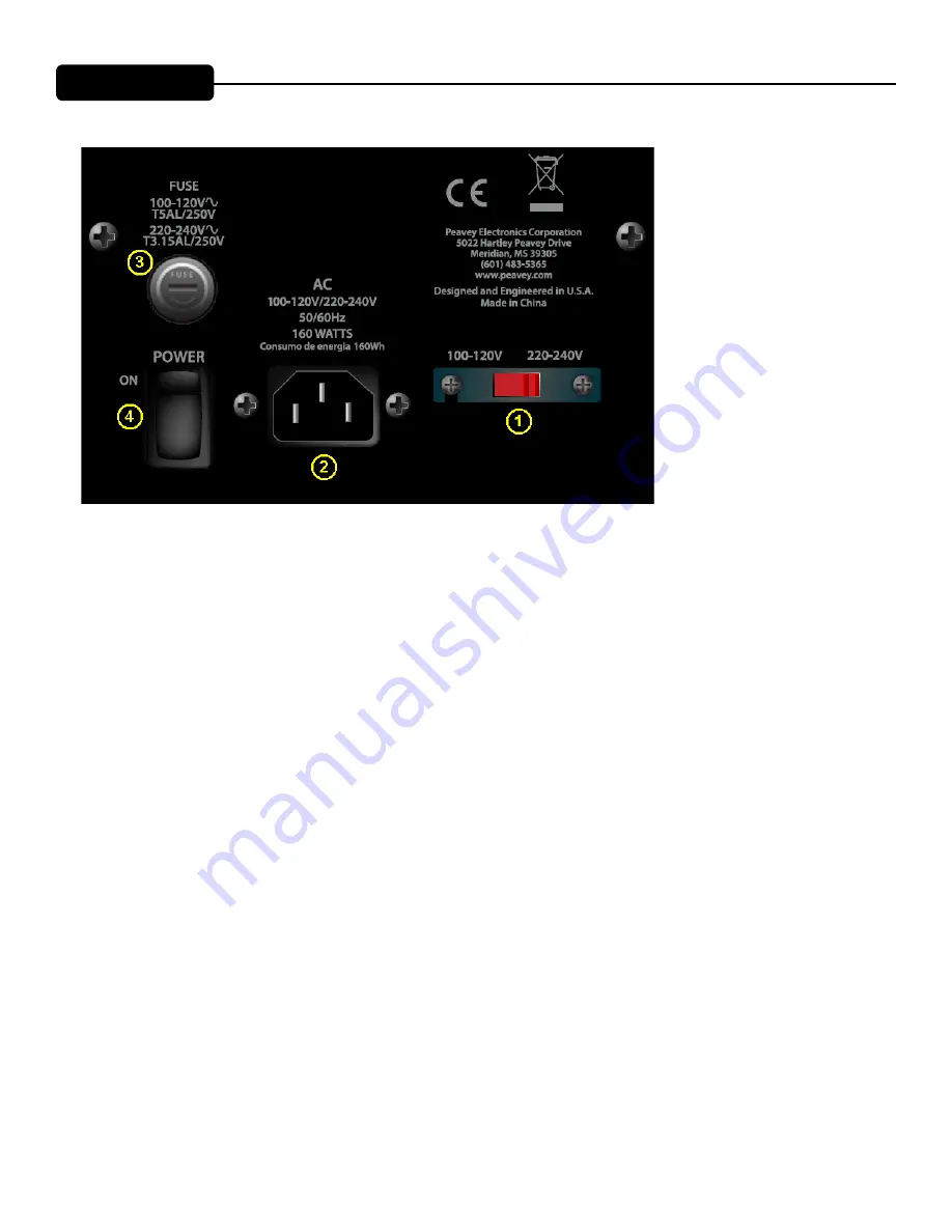
Rear Panel
Loudspeaker System Specifications
_ PAGE _1_
The
XS™12 Sub
speaker system power amplifier providing the power is a low-
distortion reliable fan-cooled unit providing a total of 1,000W peak available
power for the system. The power supply for the power amp is a switch mode
type for low weight and high efficiency. The amplifier features DSP processing
for the crossover functions, compression and limiting, and the low-frequency EQ.
Input is via a combo female XLR and 1/4” TRS phone jack with balanced input to
the preamp/EQ electronics, and a gain control.
A pair of High-Pass Outputs in the form of male XLR jacks provides a buffered
and balanced output signal for satellite speakers to carry the high range of the
music. A Full-Range Thru output has a male XLR connector. These outputs
allow linking of additional speaker systems, or feed of the signal to other devices,
etc.
Applications
The Peavey
XS™12 Sub
has a variety of applications such as extending the
bass performance of smaller full-range speaker systems for sound
reinforcement, public address, side fill system, karaoke or musical playback.
A typical signal source for the line-level inputs of the Peavey
XS™12 Sub
would
be a sound reinforcement mixing console (mixer) or the output from a CD player,
MP3 player or tape deck. The high-pass filtered signal from the
XS™12 Sub
would then be sent to a full-range powered speaker system, easing the burden of
deep bass from this speaker system.
REAR PANEL
BOTTOM
VOLTAGE SELECTOR SWITCH (1)
The PVs 12 Sub has a voltage selector switch to allow switching between an input power voltage range from
100VAC to 120VAC to a range from 220VAC to 240VAC, all at either 50 or 60 cycles per second (Hz). It should
be set to the proper voltage for your country out of the box. However, world conditions are such that some areas
have power line voltages differing from the voltage used by the majority of any given locale.
Be sure to check the position of the voltage selector switch to see that it matches the power line voltage used
locally. The red slider slot should be toward the voltage required that is printed on the rear panel.
If it does not match, then to change the voltage to the correct one, follow the steps outlined below.
Changing the Voltage Range of the PVs 12 Sub
First, make sure the PVs 12 Sub is disconnected from the power line, and that the power switch (4) is in the OFF
position.
Second, unscrew the screws holding the clear switch protector on the voltage selector switch (1) just a little, just
enough to allow rotation of the clear switch protector. The screws DO NOT need to be unscrewed very far.
Third, rotate the clear plastic protector about 90 degrees to uncover the voltage selector switch. One side of the
cover has a slot; the other just a hole. The side with the hole is the side that pivots.
Fourth, using a small flat blade screwdriver, push the red selector switch slide plate to the other side from where
it was. The red slider slot should be toward the desired voltage that is printed on the rear panel.
Fifth, rotate the clear plastic protector back underneath the loosened screws, and tighten one down while hold-
ing the clear plastic protector in place. Tighten the other screw down, and make sure both screws are tight.
If the screws are over-tightened, this could damage the voltage selector switch clear plastic cover, so do not apply
excessive force to the screws!
Summary of Contents for PVs 12 Sub
Page 1: ...www peavey com PVs 12 Sub Enclosure Operating Manual ...
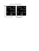
Page 17: ...Typical Hook up Connections Loudspeaker System Specifications ...
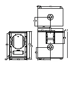
Page 20: ...19 50 768 224 8 819 ...
Page 23: ......
Page 24: ......


