background image

asegurarse de que todos los cables CA cumplan con los códigos y reglamentaciones locales. También se recomienda la 
utilización de un prensacables correctamente sujeto al gabinete para liberar presión sobre el cable de alimentación IEC 
conectado al módulo del amplificador (2) de modo que no se pueda tirar del cable ni se pueda aflojar debido a la vibración.

UsO DeL pVXp

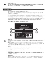
 12 cOn Un TÚneL De pOsTe De sUBWOOFer

El soporte incorporado permite el uso con el Peavey

®

 SP

®

 118 Sub y el poste accesorio diseñado para utilizar con el mismo, 

número de pieza Peavey 00326530. El poste utilizado mide 51-3/4” de largo y tiene un diámetro nominal de 1-3/8”. Siempre 
asegúrese de colocar el subwoofer usado de esta forma en una superficie plana, nivelada y estable.

UsO DeL pVXp 12 cOn Un sOpOrTe De ALTAVOZ

El PVXp 12 tiene una tapa para el montaje de soporte en la parte inferior de tal forma que el sistema se puede montar 

en un poste estándar de 1 -3/8” (36 mm) de diámetro. Cuando se usan soportes o postes, asegúrese de observar estas 

precauciones:

A. Verifique las especificaciones del soporte o poste para asegurarse de que puede soportar el peso del PVXp 12 (43 
lbs. /19,5 kg), y observe todas las precauciones de seguridad indicadas por el fabricante del soporte, incluida la 
altura máxima del soporte.

Siempre coloque el soporte en una superficie plana, nivelada y estable y asegúrese de extender totalmente las patas 
del soporte según las instrucciones del fabricante.

Intente asegurarse de que las patas del soporte se orienten de tal forma de evitar el peligro de tropezar con ellas al 
acercarse al soporte. Nunca bloquee el paso con las patas del soporte.

Intente colocar los cables de tal forma que las personas no se tropiecen con ellos ni se caiga el altavoz. El uso de 
cinta para cables, canales o protecciones para cables u otro dispositivo apropiado para sujetar/cubrir los cables se 
deben considerar e implementar.

Al instalar o desinstalar el altavoz del soporte, se recomienda contar con la asistencia de otra persona, ya que puede 
ser difícil "encontrar el orificio" y hacer coincidir la tapa del soporte con el poste del soporte mientras se sostiene el 
sistema del altavoz PVXp 12 a la altura del brazo. También sería de ayuda que alguien sujetase el soporte del altavoz 
y el poste mientras se desmonta el PVXp 12 del poste de soporte. Esto evitará que el PVXp 12 saque el poste con él.

Al usar los soportes en el exterior, nunca coloque carteles ni banderas a los soportes o al sistema de altavoz PVXp 
12, ya que los vientos fuertes pueden ocasionar la caída del altavoz. Si existe la posibilidad de condiciones ventosas, 
puede ser prudente considerar poner un contrapeso o bloquear las patas del soporte para impedir que el sistema de 
altavoz PVXp 12 caiga.

cOneXión De UnA seÑAL AL pVXp 12

Existen diferentes formas de entrar una señal al PVXp 12.

La entrada (4) proporciona una entrada de nivel de línea o micro balanceada, permitiendo el uso de un conector de teléfono 
tipo TRS de 1/4" (tip-ring-sleeve) o un conector XLR macho.

¡No conecte los cables a los enchufes mientras la unidad está ENCENDIDA y el volumen es alto! Si bien un cable estándar 

de un extremo equipado con un enchufe de teléfono de 1/4" funcionará bien y los circuitos de entrada balanceada de 
las entradas proporcionarán un cierto rechazo a las interferencias, un cable balanceado que usa un enchufe de teléfono 
balanceado TRS de 1/4" o el enchufe XLR proporcionará un rechazo de interferencia y rendimiento superior.

En ocasiones, con difíciles problemas de interferencia, será útil levantar la tierra blindada (Conector #1 de un XLR) en un 

cable balanceado en el extremo del PVXp 12. Verifique con cuidado los cambios en la entrada, siempre bajando el volumen 
antes de enchufar y desenchufar cables o realizar cambios en la conexión a tierra.

Se recomienda el uso de cables de alta calidad para el PVXp 12, ya que usualmente tienen un mejor blindaje y los materiales 
proporcionarán una mayor confiabilidad a largo plazo. La mejor opción es utilizar un cable protegido y balanceado con el 
largo exacto para alcanzar el PVXp 12. Es buena idea dejar alguna holgura en la entrada al PVXp 12 o pegar los cables hacia 
abajo o introducirlos bajo una canaleta para que nadie tropiece con ellos o tire el PVXp 12 cuando está montado en un 
soporte.

AJUsTe DeL cOnTrOL De niVeL

Le PVXp 12 est équipée d’une commande de niveau (6) sur l'entrée pour faciliter son utilisation dans nombre d’applications. 
Lorsque la commande de niveau est réglée à fond dans le sens horaire, le gain est maximum et la sensibilité d'entrée 
est de 0,54 V RMS pour la pleine sortie nominale avec la prise TRS (1/4") et de 0,12 V RMS avec la partie XLR de la prise. 
Lorsque l’enceinte PVXp 12 est animée à partir d'une console de mixage, il est préférable de réduire la sensibilité d'entrée 

Summary of Contents for PVXp 12

Page 1: ...www peavey com PVXp 12 Two Way Bi Amped Sound Reinforcement Enclosure Operating Manual...

Page 2: ...paration de l appareil un r parateur Peavey agr AVIS Dans le but de reduire les risques d incendie ou de decharge electrique cet appareil ne doit pas etre expose a la pluie ou a l humidite et aucun o...

Page 3: ...A CUIDADO Para evitar o risco de choque el trico n o remova a cobertura Cont m pe as n o repar veis pelo usu rio Entregue todos os consertos apenas a pessoal qualificado ADVERT NCIA Para evitar choque...

Page 4: ...KOREAN ARABIC CHINESE JAPANESE...

Page 5: ...ck rear support should be provided 17 Note for UK only If the colors of the wires in the mains lead of this unit do not correspond with the terminals in your plug proceed as follows a The wire that is...

Page 6: ...po use alg n tipo de apoyo trasero 17 Nota para el Reino Unido solamente Si los colores de los cables en el enchufe principal de esta unidad no corresponden con los terminales en su enchufe proceda de...

Page 7: ...dez comme suit a Le connecteur vert et jaune doit tre connectrer au terminal not E indiquant la prise de terre ou correspondant aux couleurs verte ou verte et jaune du guide b Le connecteur Bleu doit...

Page 8: ...ischen Schlag und Erdung zu Schlie en Sie nur an die Stromversorgung der Art an die am Ger t neben dem Netzkabel angegeben ist 16 Wenn dieses Produkt in ein Ger te Rack eingebaut werden soll muss eine...

Page 9: ...se tukea takaosastaan 17 Note for UK only If the colors of the wires in the mains lead of this unit do not correspond with the terminals in your plug proceed as follows a The wire that is colored gree...

Page 10: ...the colors of the wires in the mains lead of this unit do not correspond with the terminals in your plug proceed as follows a The wire that is colored green and yellow must be connected to the termin...

Page 11: ...n 16 Hvis dette produktet skal plasseres i en utstyrsreol m det etableres st tte p baksiden 17 Note for UK only If the colors of the wires in the mains lead of this unit do not correspond with the ter...

Page 12: ...netsnoer 16 Als dit product in een apparatuurrek gemonteerd moet worden moet voor achterondersteuning worden verzorgd 17 Note for UK only If the colors of the wires in the mains lead of this unit do...

Page 13: ...posta vicino al cavo di alimentazione 16 Se questo prodotto deve essere montato a rack necessario sostenerlo anche nella parte posteriore 17 Nota per UK Se i colori dei fili nel cavo di alimentazione...

Page 14: ...nit do not correspond with the terminals in your plug proceed as follows a The wire that is colored green and yellow must be connected to the terminal that is marked by the letter E the earth symbol c...

Page 15: ...be connected to the terminal that is marked by the letter E the earth symbol colored green or colored green and yellow b The wire that is colored blue must be connected to the terminal that is marked...

Page 16: ...d yellow must be connected to the terminal that is marked by the letter E the earth symbol colored green or colored green and yellow b The wire that is colored blue must be connected to the terminal t...

Page 17: ...connected to the terminal that is marked by the letter E the earth symbol colored green or colored green and yellow b The wire that is colored blue must be connected to the terminal that is marked wit...

Page 18: ...ARABIC 1 2 3 4 5 6 7 8 9 10 11 12 13 14 15 16 17 E N L 18 19 20 8 90 6 92 4 95 3 97 2 100 2 1 1 102 1 105 2 1 110 4 1 115...

Page 19: ...oli ja sit k ytet n vain 13 elokuuta 2005 j lkeen valmistetuissa laitteissa Juiste verwijdering van dit product Deze markering geeft aan dat dit product nergens in de Europese Unie met ander huishoude...

Page 20: ...can radiate radio frequency energy and if not installed and used in accordance with the instructions may cause harmful interference to radio communications However there is no guarantee that interfer...

Page 21: ...nd a RX14 titanium diaphragm dynamic compression driver mounted on a 100 by 50 degree coverage Quadratic Throat Waveguide Its sleek modern appearance coupled with excellent performance offer an outsta...

Page 22: ...ter should be used and the third wire should be grounded properly To prevent the risk of shock or fire hazard always be sure that the mixer and all other associated equipment are properly grounded App...

Page 23: ...ific for that module TOP OPERATING CONTROLS INPUTS OUTPUTS REAR PANEL TOP INPUT 4 The line level input is of the medium impedance balanced type The jack is a combo female XLR and 1 4 TRS connector SPE...

Page 24: ...can make the sound level seem much lower than it actually is This system is capable of SPLs in excess of 127 dB at 1 M from the speaker Flying the PVXp12 IMPORTANT SAFETY INFORMATION FOR THE MOUNTING...

Page 25: ...olt should not exceed 3 4 approx 20 mm WARNING note to structural engineer The thread insertion depth past the surface of the cabinet of the end of the mounting bolt should not be more than 0 787 20 m...

Page 26: ...speaker stand and pole down while the PVXp 12 is removed from the stand pole This prevents the PVXp 12 from pulling the pole up with it When using stands outdoors never attach banners or flags to the...

Page 27: ...an arc suppression capacitor to help during turn off and tends to make a clean disconnect from the AC power while the power cord IEC connector can make intermittent contact before finally becoming fu...

Page 28: ...eed additional powered units or a subwoofer to provide enough sound output or coverage In this case try turning the mixer levels down a little to see if that clears things up If after checking all the...

Page 29: ...ossover at 2 8 kHz The low frequencies shall be processed to provide bass boost subsonic filtering and overall response shaping and the high frequencies shall be equalized for response shaping The enc...

Page 30: ...et Four rubber feet provide vibration free floor or stage use and a molded in stand mounting cup is on the bottom Dimensions H x W x D Front 24 50 in x 16 10 in x 15 00 in 622 mm x 409 mm x 381 mm Rea...

Page 31: ...203 9 mm 6 65 168 9 mm 5 127 mm 2 76 70 mm 24 609 5 mm 16 408 mm 14 88 378 mm 9 34 237 2 mm 977 24 8 mm 5 127 mm 7 87 200 mm 5 96 151 4 mm 2 76 70 mm 7 mm 00 mm 20 mm 3 62 92 mm 2 95 75 mm 8 203 9 mm...

Page 32: ...woofer profesional y de alta resistencia de 12 y un controlador de compresi n din mico con diafragma de titanio RX14 instalado en un Waveguide de garganta cuadr tica de cobertura de 100 x 50 grados S...

Page 33: ...te Para prevenir el riesgo de descarga el ctrica o incendio siempre aseg rese de que la mezcladora y los dem s equipos asociados tengan una conexi n a tierra adecuada ApLicAciOnes El Peavey PVXp 12 ti...

Page 34: ...pAneL TrAserO enTrADAs 4 La entrada a nivel de l nea es de tipo balanceada con impedancia media El enchufe 2 es un conector combinado hembra XLR y un conector TRS 1 4 NOTA ESPECIAL La entrada normal...

Page 35: ...ede hacer que el nivel de sonido parezca mucho menor que lo que es en realidad Este sistema tiene una capacidad de SPL superior a 127 dB a 1 metro del altavoz MOnTAJe Y cOLOcAci n en ALTUrA DeL pVXp 1...

Page 36: ...roximadamente 12 mm Cuando utilice un soporte de instalaci n Peavey Versamount 70 y una arandela de bloqueo la longitud del perno no deber a superar 3 4 aproximadamente 20 mm ADVERTENCIA nota al ingen...

Page 37: ...el PVXp 12 del poste de soporte Esto evitar que el PVXp 12 saque el poste con l Al usar los soportes en el exterior nunca coloque carteles ni banderas a los soportes o al sistema de altavoz PVXp 12 y...

Page 38: ...a CA mientras que el conector IEC del conector de alimentaci n puede hacer un contacto intermitente antes de desconectarse por completo por ejemplo cuando se mueve el cable resOLUci n De prOBLeMAs No...

Page 39: ...para proporcionar una salida de sonido o cobertura suficiente En este caso intente reducir los niveles de la mezcladora para ver si se obtiene un mejor rendimiento Si despu s de verificar todos los p...

Page 40: ...estar construida con polipropileno moldeado por inyecci n con una clasificaci n UL contra llamas y marcos internos de refuerzo Se incorporar una manija a cada lado cerca del woofer y hacia el frente...

Page 41: ...5 00 plg 622 mm x 409 mm x 381 mm Parte posterior 22 75 plg x 8 75 plg x 15 00 plg 578 mm x 222 mm x 381 mm Peso neto 43 lb 19 5 kg especiFicAciOnes De LOs eQUipOs eLecTr nicOs Y DeL AMpLiFicADOr Ampl...

Page 42: ...rendement et une chambre de compression dynamique RX14 avec membrane en titane mont e sur un pavillon Quadratic Throat Waveguide dont le spectre de diffusion est de 100 degr s sur 50 degr s Son aspec...

Page 43: ...aptateur ad quat de mise la terre doit tre utilis de m me le troisi me fil doit tre correctement mis la terre Pour viter tout risque de d charge lectrique ou d incendie veiller imp rativement ce que l...

Page 44: ...gne est du type isol moyenne imp dance La prise est du type fiche combo femelle XLR et connecteur TRS de 6 5 mm 1 4 REMARQUE SP CIALE L entr e normale pour un niveau de ligne est la prise TRS de 6 5 m...

Page 45: ...e le niveau du son est nettement plus bas qu il l est en r alit Cette enceinte peut d livrer un niveau de pression acoustique d passant 127 dB 1 m du haut parleur sUspension DU pVXp 12 IMPORTANTE MESU...

Page 46: ...r mit de la vis d assemblage ne doit pas tre de plus de 20 mm 0 787 pour les groupes A B C et D d insert et de plus de 12 mm 0 472 pour le groupe E Si ces profondeurs d insertion de filet sont d pass...

Page 47: ...siGnAL L enceinte pVXp 12 L entr e d un signal pour l enceinte PVXp 12 peut s effectuer de diff rentes mani res L entr e 4 fournit soit une entr e de microphone ou de niveau de ligne isol e qui permet...

Page 48: ...ompl te notamment lorsque le cordon est tortill D pAnnAGe Aucune sortie S assurer en premier lieu que l enceinte est aliment e par le secteur et mise sous tension V rifier que le voyant lumineux du mo...

Page 49: ...rs des enceintes actives suppl mentaires ou un caisson de grave pour assurer un niveau de puissance ou de couverture suffisant Dans ce cas essayer d abaisser l g rement le niveau de la console de mixa...

Page 50: ...sont trait es pour assurer l amplification des graves le filtrage subsonique et la mise en forme globale de la r ponse et les hautes fr quences sont galis es pour la mise en forme de la r ponse Le cai...

Page 51: ...de gomme absorbent les vibrations au sol ou sur sc ne et une coupelle support moul e est pr sente sur le fond Dimensions H x L x P Avant 24 50 in x 16 10 in x 15 00 in 622 mm x 409 mm x 381 mm Arri r...

Page 52: ...mit Titanmembran montiert auf einem Quadratic Throat Waveguide mit einem Abstrahlwinkel von 100 mal 50 Sein schlankes modernes Erscheinungsbild verbunden mit einer hervorragenden Leistung stellt ein...

Page 53: ...erwenden und das dritte Kabel sollte ordnungsgem geerdet sein Um das Risiko eines Stromschlags oder Brandes zu vermeiden vergewissern Sie sich dass das Mischpult und alle anderen dazugeh rigen Ausr st...

Page 54: ...inPuT 4 Der Line Pegel Eingang ist ein symmetrischer Eingang mittlerer Impedanz Die Buchse ist eine weibliche Kombi XLR und 1 4 Zoll TRS Buchse SPEZIELLER HINWEIS Der normale Eingang f r den Line Pege...

Page 55: ...irklichkeit ist Dieses System kann 1 m entfernt vom Lautsprecher Schalldruckpegel ber 127 dB erzeugen AuFh ngen Des PVXP 12 WICHTIGE SICHERHEITSINFORMATIONEN F R DIE MONTAGE UND DAS AUFH NGEN DES PEAV...

Page 56: ...cht mehr als 0 472 Zoll ca 12 mm tief in das Geh use hineinragt Bei der Verwendung einer Peavey Versamount 70 Montagehalterung und Sprengringen darf die Bolzenl nge 3 4 Zoll ca 20 mm nicht berschreite...

Page 57: ...sollte am besten ein Helfer dabei sein da es sich als schwierig erweisen kann den Standfu am Stativflansch zu befestigen w hrend gleichzeitig das PVXp 12 Lautsprechersystem auf Arml nge gehalten werde...

Page 58: ...stungsverst rker und der Wandler durch Spannungsspr nge beim Ausschalten Der Ein Aus Schalter besitzt einen Lichtbogenunterdr ckungs Kondensator als Unterst tzung beim Ausschalten und trennt die Netzv...

Page 59: ...te bei hohen Mixer Ausgangspegeln zu berlastungen f hren Denken Sie auch daran dass auch das PVXp 12 obwohl es eine leistungsf hige Einheit mit hoher Ausgangsleistung ist letztendlich Grenzen besitzt...

Page 60: ...terung und eine ganzheitliche Gestaltung des Frequenzgangs zu bieten Die hohen Frequenzen werden f r die Gestaltung des Frequenzgangs abgeglichen Das Geh use wird aus ABS Kunststoff in Spritzgusstechn...

Page 61: ...uf dem Boden oder der B hne gedacht und es gibt einen integrierten Stativflansch auf der Unterseite Abmessungen H x B x T Front 24 50 Zoll x 16 10 Zoll x 15 00 Zoll 622 mm x 409 mm x 381 mm R ckseite...

Page 62: ...hroat Waveguide Il suo aspetto moderno ed elegante abbinato a prestazioni eccellenti offre un pacchetto eccezionale La cassa stampata in plastica leggera ma robusta dotata di sede per supporto ne favo...

Page 63: ...per la vostra sicurezza Se la presa non dotata di una spina di messa a terra deve essere utilizzato un adattatore di messa a terra e il terzo cavo deve essere messo a terra adeguatamente Onde evitare...

Page 64: ...RTE SUPERIORE CONTROLLI OPERATIVI INGRESSI E USCITE PANNELLO POSTERIORE PARTE SUPERIORE INGRESSO 4 L ingresso per livello di linea bilanciato ad impedenza media Il jack un connettore combo femmina XLR...

Page 65: ...etto al valore effettivo Questo sistema in grado di produrre livelli di pressione sonora superiori a 127 dB a distanza di 1 m dal diffusore SOSPENSIONE DEL PVXP 12 INFORMAZIONI DI SICUREZZA IMPORTANTI...

Page 66: ...l perno non deve superare 3 4 approx 20 mm ATTENZIONE nota per tecnici addetti alle strutture La profondit dell inserto della filettatura che supera la superficie del cabinet dell estremit del perno d...

Page 67: ...ante il sollevamento Quando si utilizzano supporti all aperto evitare di attaccare striscioni o bandiere ai supporti o alle unit PVXp 12 in quanto in caso di forte vento potrebbero trascinare e travol...

Page 68: ...o se si scuote il cavo RISOLUZIONE DEI PROBLEMI Nessun segnale di uscita Prima di tutto assicurarsi che l unit sia alimentata ed accesa Accertarsi che il LED sul modello amplificatore di potenza illum...

Page 69: ...are di ulteriori unit attive o di un subwoofer per poter fornire potenza sonora o copertura sufficiente In questo caso provare ad abbassare leggermente i livelli del mixer e verificare se il problema...

Page 70: ...8 kHz Le basse frequenze saranno elaborate per fornire un incremento dei bassi filtraggio subsonico e modellazione generale del timbro mentre le alte frequenze saranno equalizzate per modellare la ris...

Page 71: ...l utilizzo su pavimento o sul palco senza vibrazioni e una coppa di supporto incorporata nella parte inferiore Dimensioni Alt x Largh x Prof Parte frontale 24 50 x 16 10 x 15 00 622 mm x 409 mm x 381...

Page 72: ...Thru XLR 1 4 TRS Level DDT LED Contour 12 2 3 8 50 oz 1 4 RX14 DDT 800 Contour Quadratic Throat Waveguide 100 50 10 XLR 1 4 TRS XLR 1 4 TRS Thru 1 3 8 PVXp 12 12 100 50 Quadratic Throat Waveguide RX14...

Page 73: ...1 5 AC 3 OFF 1 4 PEAVEY 2 IEC AC PVXP 12 AC IEC PVXP 12 Peavey PVXp 12 OK Peavey PVXp 12 CD MP3 XLR XLR 1 4 TRS Thru XLR TRS 1 4 10 PVXp 12 M10 M8 16 1 3 2...

Page 74: ...3 ON AC PVXp 12 ON PVXp 12 PVXp12 10 Peavey 4 XLR 1 4 TRS XLR XLR 0 54 XLR 0 12 5 DDT 6 7 Contour Contour 4 5 6 7 8 9...

Page 75: ...8 9 PVXP 12 XLR 8 1 4 TRS 9 AC 4 PVXp 12 PVXp 12 PVXp 12 PVXp 12 1 SPL 127 PVXP 12 PEAVEY PVXp 12 30 3 5 4 0 4 75 5 42 A M10 B M10...

Page 76: ...3 4 20 1 5 C D 8 8 M8 1 25 3 4 20 Peavey Versamount 70 1 125 30 E 8 8 M8 1 25 0 472 12 Peavey Versamount 70 3 4 20 A B C D 0 787 20 E 0 472 12 A B 10 C D E 8 PVXp 12C D E Peavey Versamount70Plus 0045...

Page 77: ...12 1 3 8 36 PVXp 12 43 19 5 PVXp 12 PVXp 12 PVXp 12 PVXp 12 PVXp 12 PVXP 12 PVXp 12 4 1 4 TRS XLR ON 1 4 TRS 1 4 XLR PVXp 12 XLR 1 PVXp 12 PVXp 12 PVXp 12 PVXp 12 PVXp 12 6 1 4 TRS 0 54 V RMS XLR 0 12...

Page 78: ...12 PVXp 12 PVXp 12 PVXp 12 PVXP 12 AC 3 AC AC IEC AC LED ON OFF 3 ON IEC 2 1 AC PVXp 12 PVXp 12 PVXp 12 Peavey Peavey PVXp 12 AC PVXp 12 AC PVXp 12 PVXp 12 1 4 PVXp 12 1 PVXp 12 AC PVXp 12 AC PVXp 12...

Page 79: ...13 dB PVXp 12 Peavey PVXp 12 AC PVXp12 AC PVXp12 PVXp 12 Armor All PVXp 12 60 Hz 20 kHz 1 SPL 127dB Peavey Pro 12 12 Peavey RX 14 1 4 100 50 10 15 35 XLR 1 4 TRS Contour EQ 5 dB XLR 1 4 TRS Thru 20 Hz...

Page 80: ...Peavey PVXp 12 1 1 2 51 Hz 20 kHz 1 60 Hz 20 kHz 3 dB 10dB 55 Hz 1 1 97 dB 1 SPL 127dB 6 dB 100 X 50 10 15 35 12 2 3 8 50 oz RX 14 1 4 62 Hz 2 800 Hz 24 dB 24dB XLR 1 4 1 4 XLR XLR 1 4 Thru PVXp 12 AB...

Page 81: ...120 VAC 800 650 325 1 150 75 1 2 2 1 4 10 1 4 2 2 XLR 1 4 TRS 0 54 V RMS XLR 0 12 V RMS 36 dB 0 3 dB 20 Hz 20 kHz 90 dB DDT 21 dB THD IMD 0 5 100 1000 Hz 8 Peavey PVXp 12 110 220 240 VAC 50 Hz...

Page 82: ...12 TRS 1 4 XLR 2 XLR 1 4 TRS LED LED DDT 2 12 2 3 8 50 oz 1 4kg RX14 1 4 DDT 800W Quadratic Throat Waveguide 2 100 x 50 10 XLR 1 4 TRS XLR 1 4 TRS 1 3 8 PVXp 12 2 Pro 12 RX14 100 x 50 2 PA 3 45 5 2 2...

Page 83: ...1 5 AC 3 1 4 6mm Peavey IEC 2 AC IEC PVXp 12 AC PVXp 12 IEC 3 Peavey PVXp 12 Peavey PVXp 12 CD MP3 XLR XLR 1 4 TRS EQ XLR TRS 10 EQ PVXp 12 M10 1 M8 4 16 1 3 2...

Page 84: ...3 AC PVXp 12 PVXp 12 PVXp 12 10 EQ Peavey 4 XLR 1 4 TRS TRS XLR XLR TRS 0 54 XLR 0 12 LED 5 DDT 6 7 4 5 6 7 8 9...

Page 85: ...8 9 PVXp 12 XLR 8 1 4 TRS 9 AC 4 10 cm PVXp 12 PVXp 12 PVXp 12 PVXp 12 SPL 1 M 127 dB PVXP 12 PEAVEY PVXp 12 1 30 3 5 4 0 foot lbs 4 75 5 42 N m A M10 2 B M10 2 C M8 4 Peavey Versamount 70...

Page 86: ...8 8 8 1 25 mm 3 4 20 mm Peavey Versamount 70 1 125 30 mm E M8 8 8 1 25 mm 0 472 12 mm Peavey Versamount 70 3 4 20 mm A B C D 0 787 20 mm E 0 472 12 mm A B 10 mm C D E 8 mm PVXp 12 C D E PeaveyVersamou...

Page 87: ...1 3 8 36mm PVXp 12 43 lbs 19 5 kg PVXp 12 PVXp 12 PVXp 12 PVXp 12 PVXp 12 PVXP 12 PVXp 12 4 1 4 TRS XLR 1 4 TRS 1 4 XLR PVXp 12 XLR 1 PVXp 12 PVXp 12 PVXp 12 PVXp 12 PVXp 12 6 1 4 TRS 0 54 V RMS XLR...

Page 88: ...VXp 12 PVXp 12 PVXp 12 PVXP 12 AC 3 AC AC IEC AC LED 3 IEC 2 AC AC 1 AC PVXp 12 3 1 2 1 PVXp 12 PVXp 12 Peavey Peavey PVXp 12 AC PVXp 12 AC PVXp 12 PVXp 12 1 4 PVXp 12 1 PVXp 12 AC PVXp 12 AC 3 PVXp 1...

Page 89: ...dB PVXp 12 Peavey PVXp 12 AC PVXp 12 AC PVXp 12 PVXp 12 Armor All PVXp 12 60 Hz 20 kHz SPL 1M 127 dB Peavey Pro 12 12 Peavey RX 14 1 4 100 50 10 15 35 XLR 1 4 RTS 1 EQ 5 dB XLR 1 4 TRS 20 Hz 20 kHz 0...

Page 90: ...0 Hz 20 kHz 3 dB 10 dB 55 Hz 1W 1M 97 dB 1 127 dB SPL 6 dB 100 X 50 10 15 35 12 2 3 8 50 oz RX 14 1 4 62 Hz 2 800 Hz EQ 2 24 dB 4 24dB 4 EQ XLR 1 4 1 4 XLR XLR 1 4 1 PVXp 12 ABS M10 2 2 1 1 M8 4 4 x 4...

Page 91: ...120 VAC 800 650 325 1 150 75 1 2 2 k 1 4 10 k 1 4 2 2 k XLR 1 4 TRS 0 54 V RMS XLR 0 12 V RMS 36 dB 0 3 dB 20 Hz 20 kHz 90 dB DDT 21 dB THD IM 0 5 100 1000 Hz 8 Peavey PVXp 12 110 100 120 VAC 50 60 Hz...

Page 92: ......

Page 93: ......

Page 94: ...eturn shipping charges How To Get Warranty Service 1 Take the defective item and your sales receipt or other proof of date of purchase to your Authorized Peavey Dealer or Authorized Peavey Service Cen...

Page 95: ...ctive 2002 96 EC Annex IV OJ L 37 38 13 02 03 and defined in EN 50419 2005 The bar is the symbol for marking of new waste and is applied only to equipment manufactured after 13 August 2005 U S custome...

Page 96: ......
Reviews: