background image

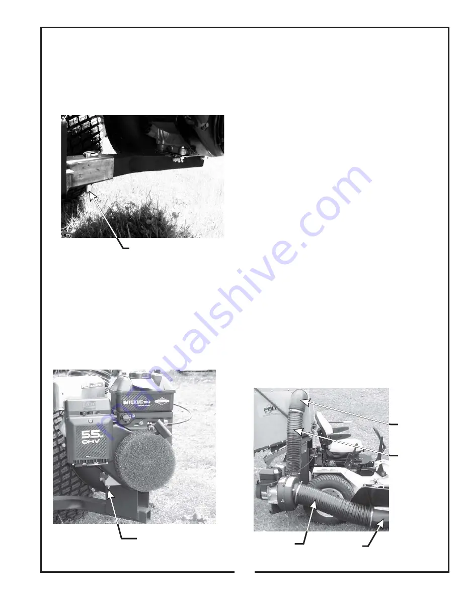
2-9 Engine/Blower/Blade Assembly

Installation

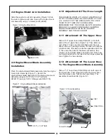
Place the engine/blower/blade assembly onto the engine
mount arm assembly (Figure 11). Secure the
engine/blower blade assembly to the engine mount arm
assembly using (4) 5/16"-18 x 1-1/2" hex bolts
P#(K1157) and (4) 5/16"-18 flange nuts P#(K1178).

2-8 Engine Mount Arm Installation

Slide the engine mount arm assembly (Figure 10) into
the outer engine mount tube. Secure the engine mount
arm assembly using (1) detent pin P#(J0248).

2-10 Adjustment Of The Hose Length

2-11 Attachment Of The Upper Hose

2-12 Attachment Of The Lower Hose

To The Engine/Blower/Blade Assembly

THE HOSES IN STEPS 2-11 AND 2-12 MUST BE CUT
TO FIT YOUR MACHINE. FOLLOW STEPS 2-11 AND
2-12. DO NOT CUT THE HOSES UNTIL YOU HAVE
TRIED TO FIT THEM ON YOUR MACHINE.
REMEMBER THAT THE HOSES HAVE TO BE LONG
ENOUGH TO ALLOW FOR ENOUGH CLAMPING
SURFACE BETWEEN THE INLET, BLOWER
ASSEMBLY, AND THE DECK BOOT.

Slide a 5”-6” upper hose clamp P#(J6011) onto both
ends of the 6” upper hose (Figure 12). Then slide one
end of the 6” hose onto the inlet. Make sure there is
about a two-inch overlap between the hose end and the
container inlet. Proceed to slide the opposite end of the
6” hose onto the outlet of the blower assembly. See
(Figure 12) for details. Make sure both ends of the hose
are clearly attached to the inlet and the blower assembly
inlet. Tighten the hose clamps.

Slide a 7”-8” hose clamp P#(J6006) over both ends of
the lower hose. Then proceed to slide the lower hose
onto the blower cone. Tighten the hose clamp. The
assembly should look like (Figure 12).

9

Figure 10 Engine Mount Arm

Figure 11 Engine/Blower/Blade Installation

5/16" x 1-1/2" Bolt

Detent Pin

Figure 12 Hose Assembly

Inlet

Upper Hose

Lower Hose

Boot

Summary of Contents for 22621223-24

Page 1: ...OPERATOR S MANUAL GRASS COLLECTION SYSTEM DESIGNED FOR ASSEMBLY OPERATION MAINTENANCE MODEL 22621223 24 toro z100 series MANUAL PART Q0309 4 00 REV 0 P PECO PECO P P P P PECO PECO PECO...

Page 2: ...yes and mind on your tractor while mowing or operating your attachment Don t let others distract you Do not attempt to operate your tractor or mower when not in the driver s seat Always stop Vac blowe...

Page 3: ...any slope This Safety Alert Symbol means This symbol is used to call attention to safety precautions that Should be followed by the operator to avoid accidents When you see this symbol carefully read...

Page 4: ...roken parts other than engines or batteries must be returned to Peco Inc PO Box 1197 Arden NC 28704 before any warranty adjustment can be authorized At the time of requesting warranty adjustment the p...

Page 5: ...charge area of the cutter deck up to the aluminum container mounted over the rear portion of the ZT frame The operator can engage the engine blower blade assembly by starting the engine Once the conta...

Page 6: ...es Insert the pins from the outside to the inside Secure with 1 5 8 washer P K0058 and 1 5 32 x 2 5 8 hair pin clip P K0088 per pivot pin Reattach the bottom ends of the door opening linkages to the m...

Page 7: ...Handle Mount Bracket Handle Grip Latch Rod Figure 4 Lift Handle Assy Figure 7 Aluminum Grass Container Assy Figure 5 Aluminum Grass Container With Handle Attached Figure 6 Latch Hook Mechanism Assembl...

Page 8: ...x 40 LOWER HOSE 1 ENGINE BLOWER BLADE ASSEMBLY 2 J6006 7 8 HOSE CLAMP 2 J6011 5 6 HOSE CLAMP 1 E6009 8 BLOWER CONE 1 A0403 MAIN FRAME ASSEMBLY 1 A0318 ENGINE MOUNT TUBE 1 A0507 WEIGHT ASSEMBLY 1 A0060...

Page 9: ...YOUR MACHINE REMEMBER THAT THE HOSES HAVE TO BE LONG ENOUGH TO ALLOW FOR ENOUGH CLAMPING SURFACE BETWEEN THE INLET BLOWER ASSEMBLY AND THE DECK BOOT Slide a 5 6 upper hose clamp P J6011 onto both ends...

Page 10: ...r lifting the weight into place Fasten the weight assembly to the mower by using 2 3 8 x 1 hex 2 16 Exhaust Diverter Installation 2 17 Tips On Mowing With The Collection System Attach the exhaust dive...

Page 11: ...andle in the away position pull the handle downward until it stops Move the handle towards the center of the mower This motion will allow the latch to lock back into collection position If you do not...

Page 12: ...____ Phone Number ____________________________ Address PeCo Inc P O Box 1197 Arden NC 28704 Phone 828 684 1234 or Toll Free 800 438 5823 Email pecoinc1 bellsouth net SECTION V PARTS AND SERVICE 5 1 Pa...

Page 13: ...13...

Page 14: ...NOTES 14...

Page 15: ...NOTES 15...

Page 16: ...P O BOX 1197 ARDEN NORTH CAROLINA 28704 800 438 5823 OR 828 684 1234 FAX 828 684 0858 EMAIL pecoinc1 bellsouth net WEBSITE WWW LAWNVAC COM P PECO PECO P P P P PECO PECO PECO...

Reviews: