17
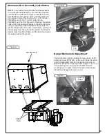
Aluminum Box Assembly Installation
NOTE:
It is recommended that two extra people assist
in mounting the Box Assembly. Two can lower the Box
onto the frame while the third person inserts the Pivot
Pins P#(K0172) through the holes. Insert the Pins from
the outside to the inside. Secure with (1) 5/8” Washer
P#(K0058) and (1) 5/32” x 2-5/8” Hair Pin Clip
P#(K0088) per Pivot Pin (Figure B). Reattach the bottom
ends of the door opening linkages to the Main Frame by
using (1) Rue-Ring Cotter Pin P#(K1437) per side. To
test the functionality of the dump mechanism, pull the Lift
Handle away from the unit, and lift upward. The Door of
the Box Assembly should open and the Box should pivot
clockwise towards the ground.
The mechanism may be adjusted in three places, at the
Adjusting Screw P#(K1435), at the Latch Hook Pivot Bolt
and the linkage Ball Joint. To change the door closure
tightness, thread the Adjusting Screw (Figure C) in or out
or by adjusting the Latch Hook Pivot Bolt within its’
mounting slot. To adjust the Latch Hook closure angle,
thread the Linkage Ball Joint in or out.
Dump Mechanism Adjustment
Rue-Ring
Cotter Pin
Adjusting
Screw
Washer
Hair Pin
Clip
Pivot
Pin
Attach
Here
Box Assembly
Figure A
Figure B
Figure C
Summary of Contents for 23651201
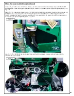
Page 24: ...24 Wire Harness Installation Continued Figure D...
Page 27: ...27 A2207 Mount Arm Tube Assembly...
Page 32: ...32 A2060_01 Mounted Drive Assembly...
Page 34: ...34 A2061_02 Drive Assembly 4 Blade Impeller...
Page 37: ...37...
Page 41: ...41...
Page 43: ...43 Notes...

