23
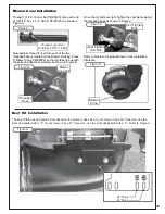
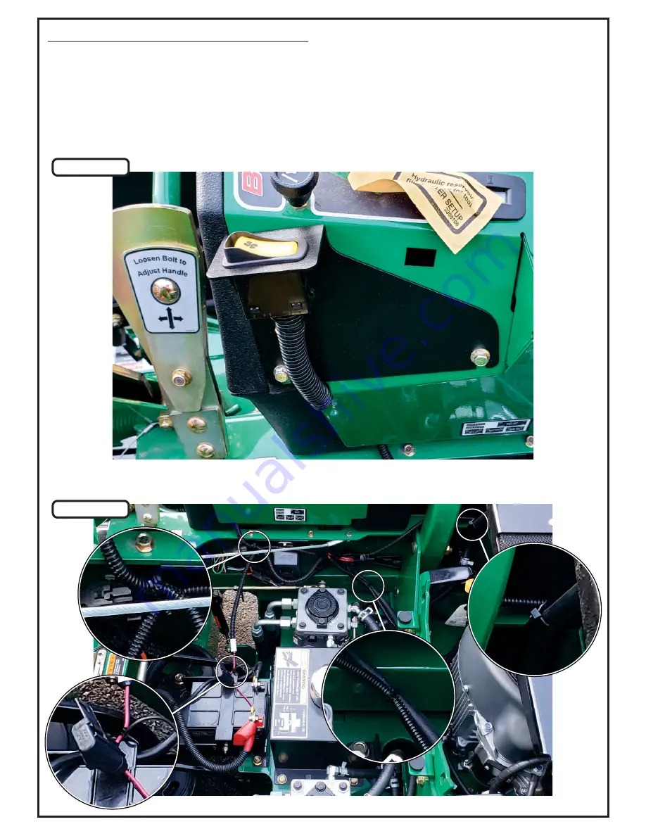
Figure B
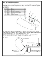
Use the Zip Ties (P#J0245) that are provided to secure the Wiring Harness in place. Refer to Figure C for the
recommended zip tie points.
Figure C
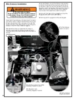
Wire Harness Installation (Continued)
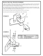
Loosen the (2) bolts located on the mower’s side panel below the mower’s controls. Align and position the Switch
Mount Bracket’s P#(B1955) slots behind the (2) bolts. Tighten the (2) bolts to secure Switch Mount Bracket. Refer to
Figure B.
Place the PTO Engagement Rocker Switch P#(P0293) into the Switch Mount Bracket. Route the Wiring Harness’ (2)
Switch Connectors up through the bottom of the side panel and connect them to the PTO Engagement Rocker
Switch. To protect the Switch Connectors, wrap the 4.6” Poly Loom P#(P0297) around the Switch Connectors and
secure using (2) Zip Ties P#(J0245). Refer to Figure B.
Summary of Contents for 23651201
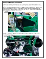
Page 24: ...24 Wire Harness Installation Continued Figure D...
Page 27: ...27 A2207 Mount Arm Tube Assembly...
Page 32: ...32 A2060_01 Mounted Drive Assembly...
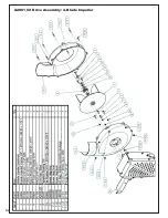
Page 34: ...34 A2061_02 Drive Assembly 4 Blade Impeller...
Page 37: ...37...
Page 41: ...41...
Page 43: ...43 Notes...


