background image

43

3. Make sure all shields are in place and in good 
    condition. Repair or replace any missing or damaged 
    shields.

4. Perform lubrication per instructions.

5. Listen for abnormal sounds, which might indicate 
    loose parts, damaged bearings, or other damage. 
    Correct any deficiency before continuing operation.

6. With the engine off, engage the blower assembly. 
    Check the belt tension and inspect the pulley belt for 
    cracks or tears.

7. Check for wear or deterioration of the upper or lower 
    hoses. If there are any portions of the hose that have 
    been torn or worn through, replace immediately.

After Each Use:

1. Clean all debris from machine especially from the 
    container, underneath the belt shields, and safety 
    decals. Replace any missing or illegible decals.

2. Inspect the unit for worn or damaged components.
    Repair or replace before the next use. Any 
    replacement component installed during repair shall 
    include the component’s current safety decal specified 
    by the manufacturers to be affixed to the component.

3. Under normal usage, the bag material is subject to 
    deterioration and wear and should therefore be
    frequently checked for necessary replacement. Any
    replacement bag should be checked to ensure 
    compliance with the original manufacturer’s
    recommendations or specifications.

4. Check belt for proper tension.

DOCUMENT THE FOLLOWING INFORMATION FOR FUTURE REFERENCE

Unit Model Number:_______________________________________________

Unit  Engine  Size:__________________________________________________

Unit Serial Number:________________________________________________

Date of purchase:________/________/_________

Dealer/Distributor Name:__________________________________________

Address: _________________________________ State:_______ Zip:_______

Phone Number: ____________________________________________________

New PECO, Inc.

10 Walden Dr | Arden, North Carolina 28704

Phone: 1-800-438-5823 | 828-684-1234

Fax: 828-684-0858

Email: 

peco@lawnvac.com

Website: www.lawnvac.com

4-2 Lubrication

Gearbox:

  NOTE: 

The gearbox is filled with 6.0 oz. of Mobilube 

HD Plus 80W-90 oil and permanently sealed. There is 
no need for scheduled lubrication. The oil level should 
only be checked if a leak is observed or if a change in 
gearbox noise is noticed.

Operators are recommended to check for leaks weekly. 
If a leak is observed, both the gasket and the seals are 
recommended to be replaced. 

Replace the oil using 5.5 oz. of the recommended 
Mobilube HD Plus 80W-90 oil. Be sure to not overfill.

Blower Assembly:

  NOTE: 

The following is for older PTO models that

      contain a greaseable zirc fitting. Newer models 
      contain maintenance-free bearings and are without
      a greasable fitting.
.
  1. On initial use: Grease the fitting on the blower shaft.
  2. Every 25 hours of use: Re-grease the grease fitting.

  NOTE:

 Use only white lithium based grease for 

      lubrication of the shaft on the blower assembly.

SECTION V - PARTS & SERVICE

5-1 Parts And Service Information

 
Collection system owners should record the name and 
telephone number of their Service Center. Your Service 
Center will be happy to supply replacement parts, 
accessories, and do any service or repairs to your 
collection system. If for any reason your Service Center 
is unable to service your collection system or supply 
replacement parts, contact New PECO, Inc. and include 
the following information on the chart below. 

Summary of Contents for 38651202

Page 1: ...M P P P PECO PECO PECO PECO PECO PECO P P P P P P P P PECO PECO R R R MANUAL PART Q0578 Initial Release October 2021 ASSEMBLY OPERATION MAINTENANCE Dixie Chopper Eagle HP Jacobsen ZT1000 Model 3865120...

Page 2: ...inum Box Assy Installation 19 Dump Mechanism Adjustment 19 Inlet Inlet Ring Debris Deflector Installation 20 SECTION PAGE Wiring Harness Installation 21 22 Length of Hose Adjustment 23 Upper Hose Inst...

Page 3: ...situation which if not avoided could result in death or serious injury It may also be used to alert against unsafe practices This signal word indicates a potentially hazardous situation which if not...

Page 4: ...rate manufacturer warranties and those companies must be contacted directly to file a warranty claim Briggs Stratton https www briggsandstratton com na en_us support warranty html 2 UNAPPROVED ALTERAT...

Page 5: ...m the normal operator s position on the mower Description The grass collection system is designed for turf maintenance where there is a need to collect the grass clippings as the mower cuts the turf I...

Page 6: ...nstalled using an arbor press or equivalent During installation opposite bearing inner race must be supported or bearing damage may occur Refer to Figure D Once the Engine Pulley Bushing is installed...

Page 7: ...holes Then remove the hardware from the lower bolt hole of the right side of the ROPS to reveal 1 bolt hole Next align the bottom 2 right bolt hole of the Right Mount Plate to the ones on the lower ri...

Page 8: ...e to the mower s rear bumper and align the bottom 2 bolt holes located on the bottom tab of the Rear Mount Plate to those on the mower s rear bumper see Figure A Secure the Rear Mount Plate relatively...

Page 9: ...sing 3 3 8 16 x 1 Carriage Bolts Item 2 and 3 3 8 16 Ny Flange Lock Nuts Item 3 Secure the Rear Mount Plate to the Right Mount Plate Using 1 3 8 16 x 1 Carriage Bolt Item 1 and 1 3 8 16 Ny Flange Lock...

Page 10: ...Lower PTO Mount Plate by using 1 3 8 16 x 1 1 2 Carriage Bolt Item 2 2 3 8 16 x 1 1 4 Carriage Bolt Item 3 and 3 3 8 16 Ny Flange Lock Nuts Item 4 Refer to Figure A Note Some parts and part features h...

Page 11: ...ake sure the back of the Receiver Tube Assy is resting against the bottom stop tab of the Lower PTO Mount Plate see Figure B Secure the Receiver Tube Assy Mount Arm to the Upper and Lower PTO Mount Pl...

Page 12: ...n the Rear Mount Plate and either Right or Left Mount Plate Secure either Main Frame Mounts to the Mount Plates by using 2 3 8 16 x 1 Carriage Bolts Item 3 and 2 3 8 16 Ny Flange Lock Nuts Item 4 PER...

Page 13: ...ount Item 3 Be sure the Main Frame Assembly is sitting on the inside of both Main Frame Mounts Secure the Main Frame Assembly by using 2 3 8 16 x 1 Carriage Bolts Item 4 and 2 3 8 16 Ny Flange Lock Nu...

Page 14: ...m Assembly is installed and secured to the mower assemble the Drive Assembly P A2061_02 Belt Guard Assembly P A2069_02 Idler Mount Assembly P A2067_02 First attach the Belt Guard Assembly P A2069_02 t...

Page 15: ...Bolt B Item 2 and 2 3 8 16 Ny Flange Lock Nuts Item 3 Refer to Figure B Leave Bolts Loose Note Orientation of bolts A B Next secure the Idler Mount Assembly P A2067_02 to the Belt Guard Assembly P A20...

Page 16: ...ed the AK83 Belt P M0315 between the Belt Guard and the Idler Mount Assembly Place belt around the Engine Drive Pulley on the underside of the mower While one person inserts a screw driver or similar...

Page 17: ...m the inside of the Boot so the threads are on the top of the Boot This will prevent grass clippings from collecting on the threads Leave the hardware loose until the boot plate has been attached to t...

Page 18: ...ighten the Ball Joint to approximately half way down the threads on the Latch Rod Attach the Ball Joint to the Latch Hook as shown in Figure D using 1 5 16 24 Hex Nut P K1444 and 1 5 16 Lock Washer P...

Page 19: ...re A Figure B Figure C Aluminum Box Assembly Installation NOTE It is recommended that two extra people assist in mounting the Box Assembly Lower the Box Assembly onto the frame Secure the Box Assembly...

Page 20: ...Inlet Item 3 Slide Inlet Item 3 Inlet Ring Item 1 against inlet hole and align four holes Fasten Inlet Ring Item 1 bottom holes using 2 5 16 IT Tooth Lock Washers Item 4 2 5 16 18 x 1 2 HHCS Item 6 Se...

Page 21: ...Bracket P B1020 then attach and secure the Safety Cover P P0073 Before routing the PTO Switch 2 locate and loosen the existing cap head screw located on the bottom right side of the mower s control pa...

Page 22: ...0086 RING TERMINAL 5 16 STUD SIZE P P0106 FEMALE DISCONNECT P P0086 RING TERMINAL 5 16 STUD SIZE P P0106 FEMALE DISCONNECT P P0280 2 WAY METRI PACK 280 SEALED MALE CONNECTOR Figure B SWITCH P J2001 FR...

Page 23: ...f the 6 Upper Hose to the Blower Outlet See Figure below for details Secure opposite end of the 6 Upper Hose to the Inlet with another Hose Clamp P J0060 Make sure both ends are securely fastened by t...

Page 24: ...If the Impeller will not move carefully hit the base of the Impeller between each vein with a hammer then try again To Replace Place Impeller Blade over the engine shaft Slide the Taper Lock Bushing 5...

Page 25: ...se 4 large carriage bolts and nuts located behind the name plate Remove and keep 2 existing nuts from the existing carriage bolts 1 from the far left and 1 from the far right Refer to Figure B With th...

Page 26: ...er Brace on the inside of the Caster and the Support Bracket on the outside of the Caster Secure the Caster Brace onto the Support Bracket by using 2 3 8 16 x 1 1 4 Carriage Bolts Item 5 2 and 2 3 8 1...

Page 27: ...ht Bracket Item 1 align the mount hole of the Weights w the hole on the Weight Bracket tab Fasten the Weight to the Weight Bracket using 1 Hitch Pin Item 3 1 and 1 Hair Pin Cotter Item 3 2 See Figure...

Page 28: ...28 A2207 Mount Arm Tube Assembly Exploded Parts View...

Page 29: ...29 A2092 Idler Arm Assembly A2067_02 Idler Mount Assembly...

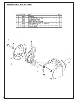
Page 30: ...30 A2058 Gearbox Sub Assembly...

Page 31: ...31 A2059_01 Clutch Sub Assembly...

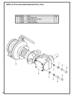
Page 32: ...32 A2057_01 Drive Assembly Exploded Parts View...

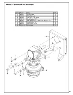
Page 33: ...33 A2060_01 Mounted Drive Assembly...

Page 34: ...34 A2039_02 Base Drive Assembly...

Page 35: ...35 A2061_02 Drive Assembly 4 Blade Impeller...

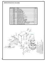
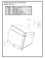
Page 36: ...36 A2100 6512 Box Assembly Standard Model Exploded Parts View...

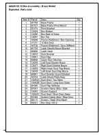
Page 37: ...37 A2226 6512 Box Assembly Base Model Exploded Parts View...

Page 38: ...38 A2226 6512 Box Assembly Base Model Exploded Parts List...

Page 39: ...39 A2107 Latch Rod Assembly...

Page 40: ...40...

Page 41: ...cal Service Center for replacement decals Part R1054 Important Hose Wear Part R1051 Warning Hearing Protection Part R1069 Warning Turn Off Blower Part R2007 Danger Never Use Hands Part R2008 Danger Ro...

Page 42: ...Check upper and lower hoses for any clogs To obtain the maximum effectiveness from your collection system the tips listed below should be followed Watch your speed Normal conditions will allow a spee...

Page 43: ...Date of purchase ________ ________ _________ Dealer Distributor Name __________________________________________ Address _________________________________ State _______ Zip _______ Phone Number _______...

Page 44: ...44...

Page 45: ...n bags are too full Low engine speed Grass is too wet Grass is too long Ground speed is too fast Worn belt Loose belt Dump more frequently Always operate collection system at full throttle Cut grass w...

Page 46: ...CO PECO PECO PECO PECO PECO P P P P P P P P PECO PECO R R R New PECO Inc 10 Walden Dr Arden North Carolina 28704 Phone 1 800 438 5823 828 684 1234 Fax 828 684 0858 Email peco lawnvac com Website www l...

Reviews: