Section I
INTRODUCTION &
DESCRIPTION
1-1 Introduction
This manual is provided to give you instructions on how
to install the Peco PTO system in combination with your
Excel Two Bag Catcher. This manual will provide
operating instructions for the Peco PTO system only.
NOTE:
For all other instructions, you will refer to your
Excel Two Bag Catcher owner’s manual and your Big
Dog owner’s manual.
1-2 Description
The grass collection system is designed for turf
maintenance where there is a need to collect the grass
clippings as the mower cuts the turf. It is also used for
picking up leaves in pre-season and post-season clean-
up. The Peco blower, mounted on the right side of the
unit, uses a belt and gearbox system from the engine
PTO shaft. Drive train protection comes through belt
slippage. The blower draws grass clippings from the
discharge area of the cutting deck back to the (2)
collection bags at the rear portion of the mower frame.
The operator can engage the blower with a spring-lock
engagement handle on the right side of the unit. Once
the bags are full with clippings, they can be easily
released for dumping.
Section II
INSTALLATION FOR USE
2-1 Preparation Of Mower
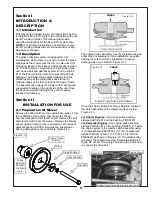
Remove the drive belt from the engine drive pulley. From
the underside of the engine, disconnect the wiring
harness attached to the electric clutch. Remove the bolt
and electric clutch from the mower. Remove the D-drive
spacer using an arbor press or equivalent. On removal,
adjacent bearing OUTER race must be supported or
bearing damage may occur. Refer to Figure 2-1a.
The engine pulley assembly must be installed using an
arbor press or equivalent. Upon Installation, opposite
bearing inner race must be supported or bearing
damage may occur. Refer to Figure 2-1c.
Once the Engine Pulley Bushing is installed, reattach
the clutch assembly to the mower and then review
Figure 2-1c.
For Kohler Engines:
Use engine pulley bushing
stamped with the #12 on the bushing, P#(S0197).
For Kawasaki Engines:
Use engine pulley bushing
stamped with the #1 on the bushing, P#(S0172). Fasten
the engine pulley to the electric clutch assembly using
(1) Clamp Washer P#(K0278), (1) 7/16” hi-collar lock
washer P#(
) and (1) 7/16”-20 x 4-1/2” HHCS
K0140
P#(K0427) as shown in Figure 2-1d. The added pulley
will power the collection system. Torque the bolt to 55
ft./lbs. Re-connect the wiring harness to the clutch and
re-connect the drive belt.
5
PRESS
Figure 2-1a
PRESS
Figure 2-1b
Engine Pulley Bushing Installation
Electric Clutch
Figure 2-1d
Engine Pulley
Bushing
Hex Bolt
Lock Washer
Pulley
Bushing
Number
Located
Here
Figure 2-1c
Clamp Washer
Pulley
Engine Pulley Assembled Into Electric Clutch
Summary of Contents for 52020901
Page 14: ...14...
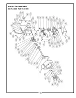
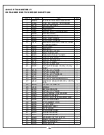
Page 15: ...15 A1815 PTO ASSEMBLY EXPLODED PARTS VIEW...
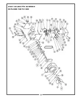
Page 17: ...17 A1841 3 BLADE PTO ASSEMBLY EXPLODED PARTS VIEW...
Page 20: ...19...
Page 21: ...NOTES...

