6
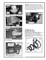
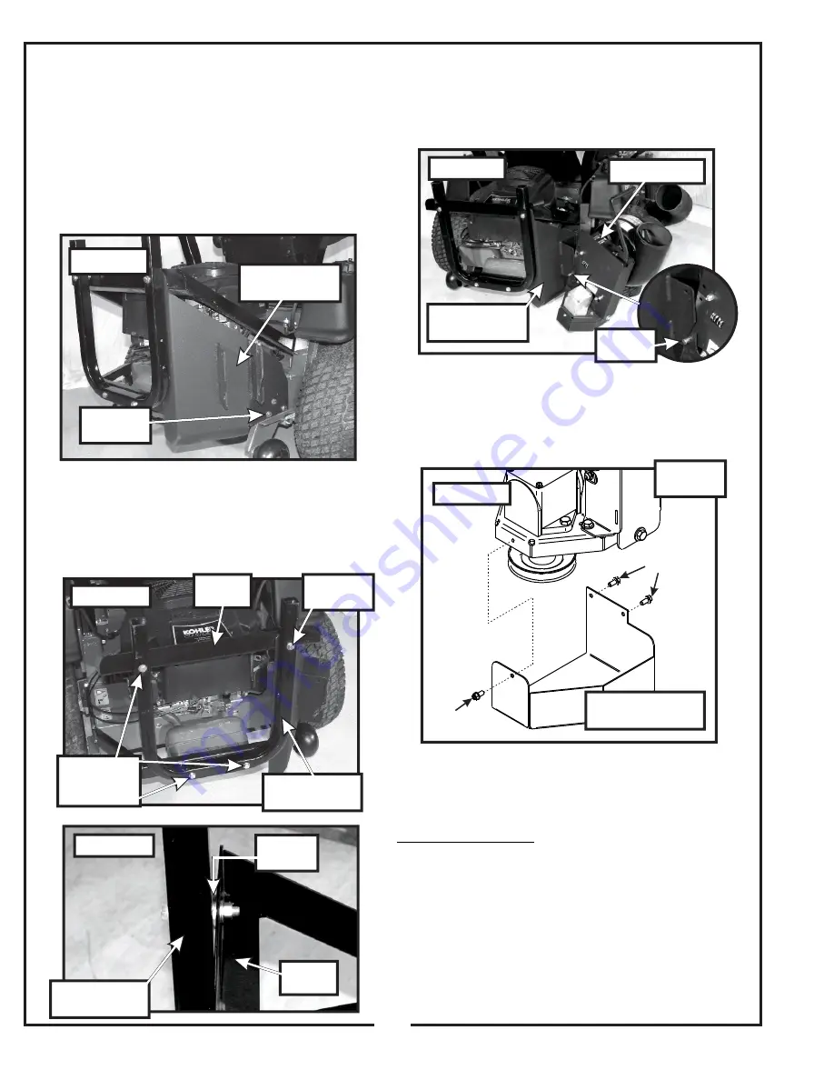
2-2 PTO Mount Plate Assembly
Installation
With the lid assembly removed, disconnect the frame
mounting tube and bumper from the bumper tie. Position
the PTO mount plate assembly P#(A1816) as shown in
Figure 2-2a. Use the existing hardware from the bumper
tie to secure the PTO mount plate assembly to the
bumper tie. Leave the hardware loose until the frame
mounting tube is re-attached.
Secure the frame mounting tube to the frame support tie
using the existing hardware from the frame tube. You will
add (1) washer P#(K1446) between the frame tube and
support tie and (2) washers between the frame tube and
bumper tie. Tighten all the hardware at this time. Refer to
Figure 2-2b and 2-2c.
2-3 PTO Assembly Installation
Insert the PTO assembly P#(A1815) into the slots on the
PTO mount plate assembly as shown in Figure 2-3a.
Remove the gear box pulley guard P#(B0478) and (3)
1/4”-20 x 1/2” HHSTS P#(K0353) from the PTO
assembly in preparation for the belt installation. Refer to
Figure 2-3b.
2-4 Belt Installation/Removal and
Adjustment
Installation/Removal:
With the PTO mount pin
P#(B0274) removed, loosen the (4) 5/16”-18 x 3/4”
HHCS P#(K1153) that secure the gear box to the PTO
assembly. Loosen the adjustment bolt (1) 3/8”-16 x 2”
hex bolt P#(K0348). Slide the gearbox towards the
mower until there is enough clearance for the kevlar belt
to slide over both the engine and gearbox pulleys. Install
the A54K kevlar belt P#(M0255). Insert the PTO mount
pin P#(B0274), and secure the pin with (1) hair pin clip
P#(K0086).
Refer to Figures 2-4a through 2-4e.
Existing
Hardware
PTO Mount
Plate Assembly
Figure 2-2a
Add Washer
To Existing
Hardware
Existing
Hardware
Figure 2-2c
Figure 2-2b
Frame
Mounting Tube
Support
Tie
Support
Tie
Frame
Mounting Tube
Add
Washers
Figure 2-3a
PTO Assembly
PTO Mount
Plate Assembly
Mounting
Slots
Figure 2-3b
Remove
Hardware
Remove Gear Box
Pulley Guard
Remove
Hardware
PTO
Assembly
Summary of Contents for 52020901
Page 14: ...14...
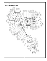
Page 15: ...15 A1815 PTO ASSEMBLY EXPLODED PARTS VIEW...
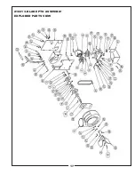
Page 17: ...17 A1841 3 BLADE PTO ASSEMBLY EXPLODED PARTS VIEW...
Page 20: ...19...
Page 21: ...NOTES...

