11
Exhaust Deflector Installation
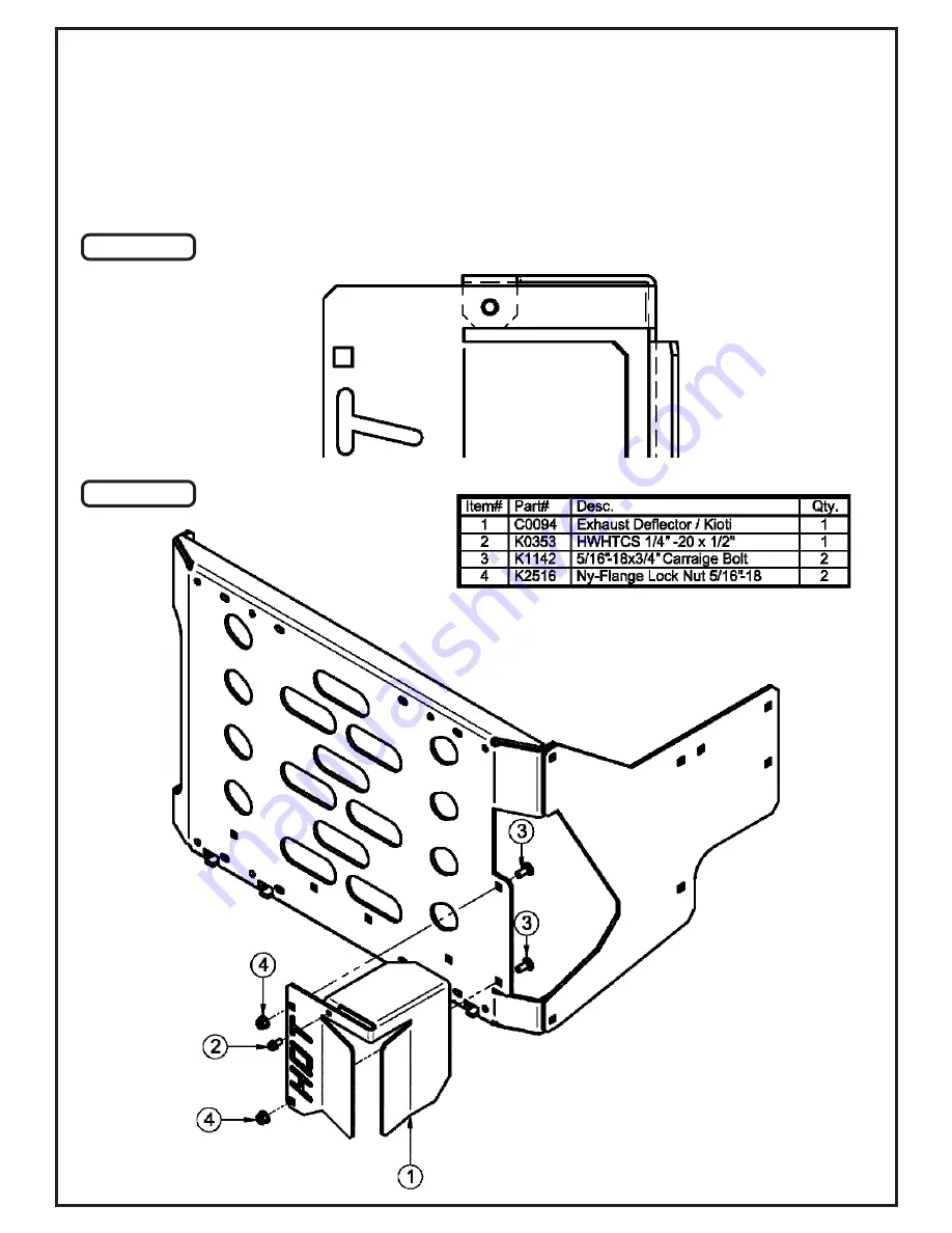
To install the Exhaust Deflector (Item #1), Fasten a 1/4”-20 x 1/2” HWHTCS self-tapping screw (Item #2) between the
front bolt hole and the rear tab bolt hole of the Exhaust Deflector. Refer to Figure A. This will help keep the Deflector
stable.
Next, align the carriage bolt holes of the Exhaust Deflector to the carriage bolt holes located on the tab of the Rear
Frame Bracket. Secure the Exhaust Deflector using (2) 5/16”-18 x 1” Carriage Bolts (Item #3) and (2) 5/16”-18 Ny-
Flange Lock Nuts (Item #4). Refer to Figure B.
Figure A
Figure B
Summary of Contents for 54120901
Page 24: ...24 A2194_01 PTO R Base Assembly Exploded Parts View...
Page 25: ...25 A2266 PTO R Assembly Exploded Parts View A2194_01 PTO R Base Assembly Parts List...
Page 26: ...26 A2266 PTO R Assembly Exploded Parts View...
Page 27: ...27 A1137_01 Handle Extension Kit Exploded Parts View...
Page 28: ...28 A2101 Top Assembly Exploded Parts View...
Page 29: ...29 A2222 Top Assembly Base Model Exploded Parts View...
Page 30: ...30...
Page 34: ...34...


