14
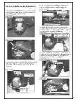
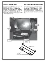
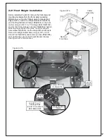
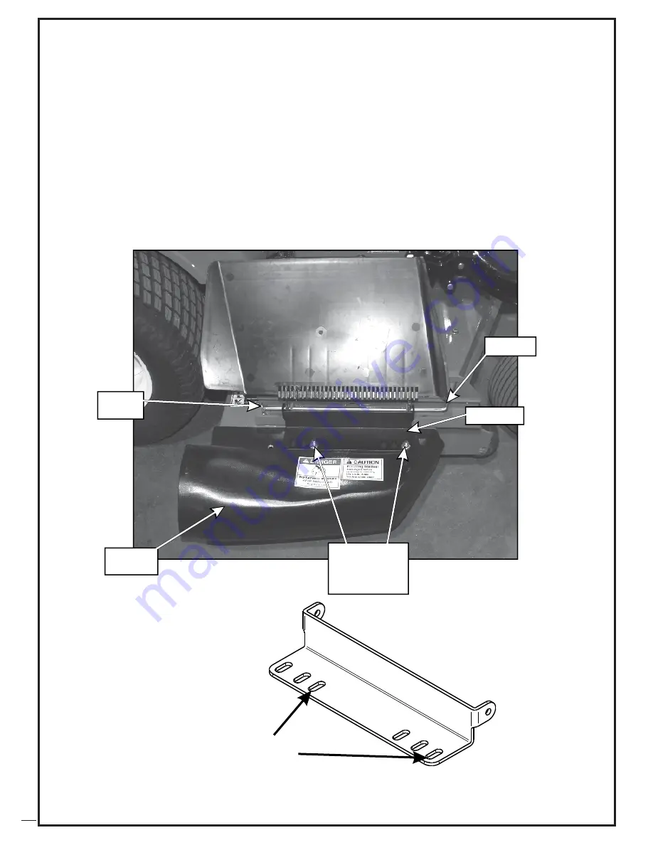
Secure the boot plate P#(B0820) to the aluminum boot
P#(E1902) using (2) 3/8”-16 x 1” carriage bolts
P#(K1182) and (2) 3/8”-16 nylon flange locknuts
P#(K2038). Insert the carriage bolts from the inside of
the boot so the threads are on the top of the boot. This
will prevent grass clippings from collecting on the
threads. Leave the hardware loose until the boot plate
has been attached to the mower deck. Refer to Figure 2
-13a and 2-13b for reference.
2-13 Boot Plate Installation
Remove the hardware from the grass deflector and
insert (1) boot rod P#(B4331) into the grass deflector
mounting holes as shown in Figure 2-13a. Secure the
boot rod using (1) hair pin clip P#(K0099). With the
carriage bolts from Section 2-13a still loose, adjust the
position of the boot so that there is no gap between the
mower deck and the boot. Tighten the hardware at this
time.
2-14 Boot To Mower Deck Installation
Boot Rod
(2) 3/8”-16 x 1”
Carriage Bolts
(2) 3/8”-16
Locknuts
Boot Plate
Aluminum
Boot
Hair Pin
Clip
Figure 2-13a
Figure 2-13b
Boss XL
Mounting Holes
Summary of Contents for Pro 12 DFS 49621203
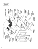
Page 18: ...18 A0794 ALUMINUM GRASS CONTAINER EXPLODED VIEW...
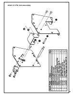
Page 19: ...19 A1841_01 PTO Arm Assembly...
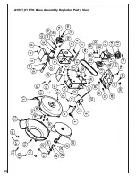
Page 20: ...20 A1941_01 PTO Base Assembly Exploded Parts View...
Page 21: ...21 A1941_01 PTO Base Assembly Exploded Parts List...
Page 22: ...22 A0623 PTO Assembly w Small Pulley Guard Exploded Parts View...
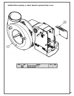
Page 23: ...23 A1950 PTO Assembly w Heat Guard Exploded Parts View...
Page 24: ...24...
Page 28: ...28...

