9
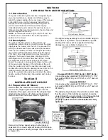
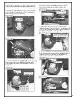
2-6 Belt Installation and Adjustment
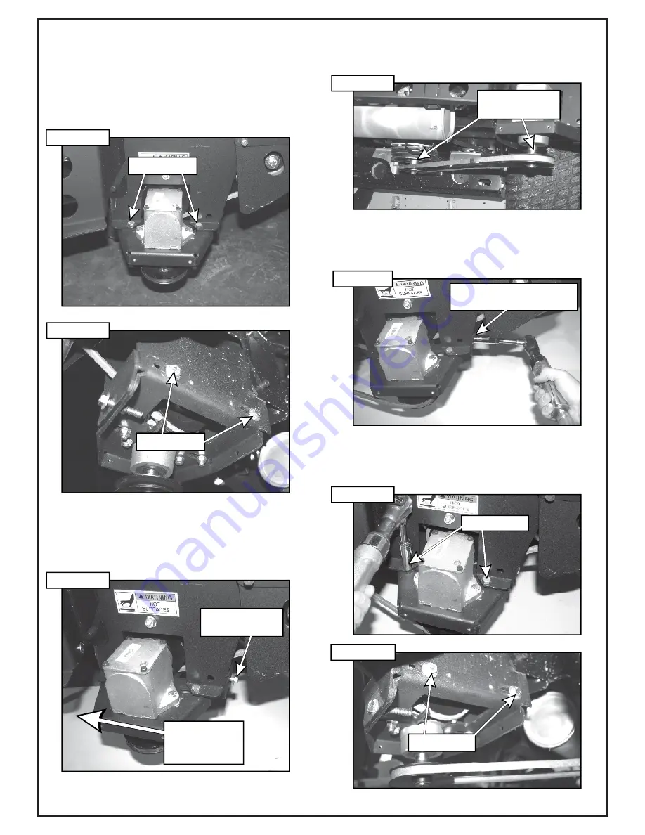
Loosen the (4) bolts P#(K1191), (2) on each side, that
secure the gear box assembly to the PTO assembly
P#(A1950) (Figure 2-6a and 2-6b).
Loosen the adjustment bolt P#(K0348) until the gear box
assembly is at its far left adjustment (the gear box is
moved toward the mower’s engine pulley). Refer to
Figure 2-6c.
Once the correct tension of the belt is achieved, tighten
the (4) bolts that secure the gear box assembly. Refer to
Figures 2-6f and 2-6g. Replace the belt guard and
hardware that was removed in Section 4.
2-
Connect the belt A57K P#(M0256) from the engine
pulley to the lower gear box pulley (Figure 2-6d).
To tension the drive belt, turn the adjustment bolt
clockwise (Figure 2-6e) until there is 1” of deflection, with
10-11 lbs. of pressure, at the center of the belt between
the engine pulley and the gear box pulley.
Loosen Bolts
Figure 2-6a
Figure 2-6b
Loosen Bolts
Figure 2-6c
Loosen The
Adjustment Bolt
Slide Gear Box
Towards The
Engine Pulley
Connect Belt
To Both Pulleys
Figure 2-6d
Figure 2-6e
Figure 2-6f
Figure 2-6g
Tighten Bolts
Tighten Bolts
Tighten The Adjustment
Bolt To Tension The Belt
Summary of Contents for Pro 12 DFS 49621203
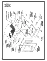
Page 18: ...18 A0794 ALUMINUM GRASS CONTAINER EXPLODED VIEW...
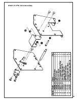
Page 19: ...19 A1841_01 PTO Arm Assembly...
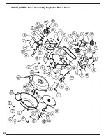
Page 20: ...20 A1941_01 PTO Base Assembly Exploded Parts View...
Page 21: ...21 A1941_01 PTO Base Assembly Exploded Parts List...
Page 22: ...22 A0623 PTO Assembly w Small Pulley Guard Exploded Parts View...
Page 23: ...23 A1950 PTO Assembly w Heat Guard Exploded Parts View...
Page 24: ...24...
Page 28: ...28...

