10
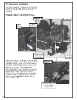
PTO Assembly Installation
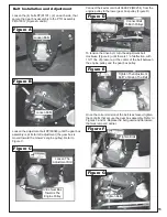
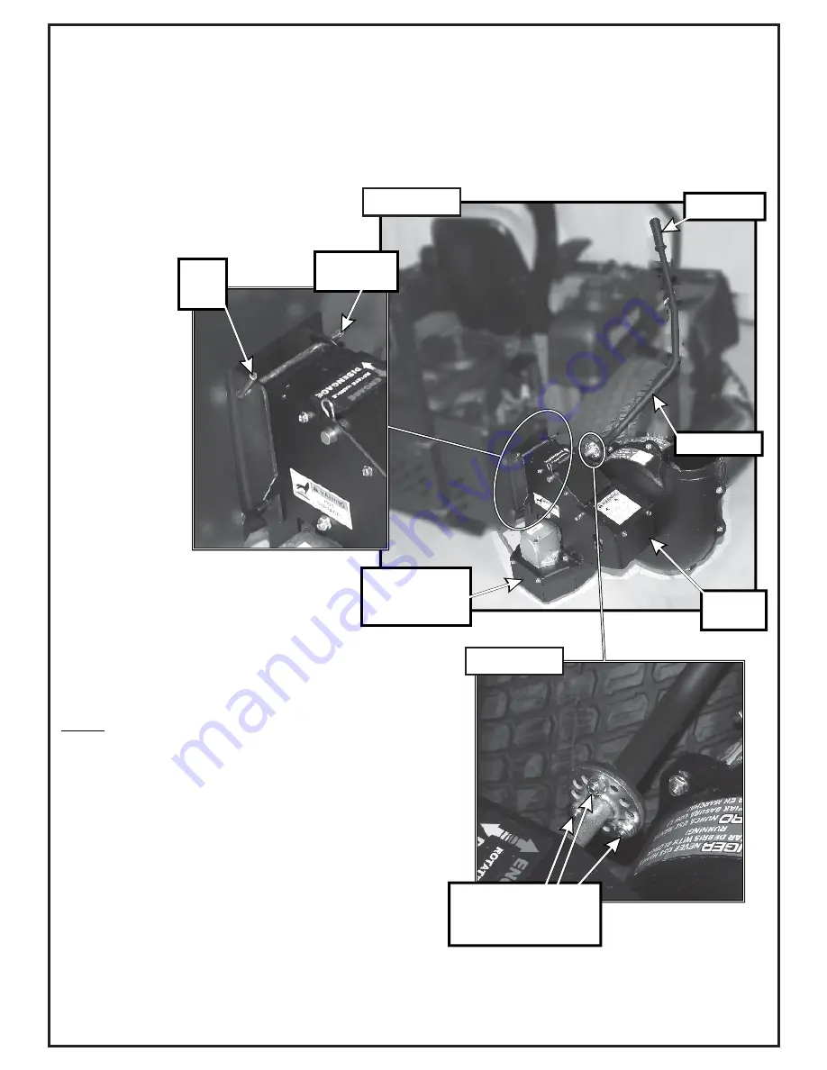
Insert the PTO assembly P#(A0623) into the slots on the
PTO mount plate assembly. Secure the PTO assembly
with (1) mount pin P#(B0274) and (1) hair pin clip
P#(K0086).
Remove the engine pulley guard and hardware in
preparation for the belt installation. Refer to Figure A.
Attach the PTO handle P#(A0626) to the PTO assembly
using (3) 1/4”-20 x 3/4” HHCS P#(K1222) and (3) 1/4”-20
nylon flange locknuts P#(K2014). Attach the handle grip
P#(J0522) to the PTO handle. Refer to Figure A and B.
NOTE:
The PTO Handle can be adjusted, after
performing installation,to achieve proper belt adjustment.
To adjust the handle, remove (3) 1/4”-20 x 3/4” HHCS
P#(K1222) and (3) 1/4”-20 nylon flange locknuts
P#(K2014), rotate handle until positioned in the desired
location (while aligning holes) and reattach. The bolts
should be kept approximately 120 degrees apart to
ensure proper fastening.
(3) 1/4”-20 x 3/4” HHCS
(3) 1/4”-20 Nylon
Flange Locknut
Handle Grip
PTO Handle
PTO
Mount
Pin
Insert
Hairpin Clip
Remove Engine
Pulley Guard
and Hardware
PTO
Assembly
Figure A
Figure B
Summary of Contents for Pro 12 DFS 52621201
Page 16: ...16 ALUMINUM GRASS CONTAINER EXPLODED VIEW A0614 K1442 V1 131 6...
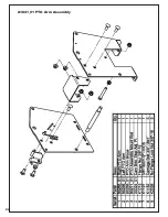
Page 22: ...22 A1841_01 PTO Arm Assembly...
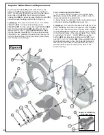
Page 23: ...23 A1941_01 PTO Base Assembly Exploded Parts View...
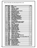
Page 24: ...24 A1941_01 PTO Base Assembly Exploded Parts List...
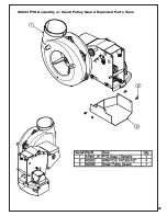
Page 25: ...25 A0623 PTO Assembly w Small Pulley Guard Exploded Parts View...
Page 26: ...26...
Page 30: ...30...
Page 31: ...31 NOTES...


