14
NOTE:
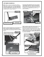
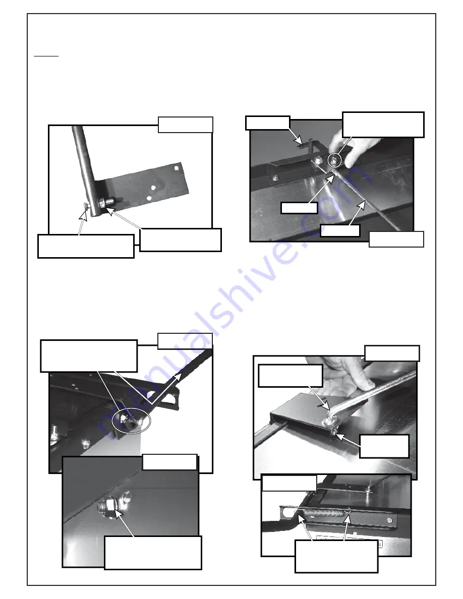
Before continuing the lift handle installation,
have someone assist you in turning the grass container
upside down. Insert (1) 3/8”-16 x 2” HHCS P#(K1208)
into the lift handle P#(A0614), and secure with (1) 3/8”-
16 flange nut P#(K1215). Thread the flange nut onto the
bolt upside down, as shown in Figure A.
Lift Handle Installation
Slide the lift handle through the slot on the handle mount
bracket. Insert the lift handle into the box frame as
shown in Figure B, and secure using (1) 3/8”-16 flange
nut P#(K1215) on the inside of the container as shown in
Figure C.
Fasten the ball joint P#(K1442) to the end of the latch
rod P#(A0620). Tighten the ball joint to approximately
half way down the threads on the latch rod. Attach the
ball joint to the latch hook as shown in Figure D, using
(1) 5/16”-24 hex nut P#(K1444) and (1) 5/16” lock
washer P#(K0043).
Attach the other end of the latch rod to the lift handle, as
shown in Figure E. Attach on end of the spring
P#(J0176) to the lift handle and the other end of the
spring to the handle mount bracket as shown in Figure F.
Adjust the ball joint up or down on the latch rod threads
until the latch hook closes completely. After adjusting the
latch hook, secure the latch rod to the lift handle using
(1) cotter pin P#(K0094).
Insert (1) 3/8”-16 x 2”
HHCS Into The Lift Handle
Secure With
(1) 3/8”-16 Flange Nut
Slide Lift Handle Through
Handle Mount Bracket And
Fasten To Box Frame
Use (1) 3/8”-16 Flange Nut
On The Inside Of The
Grass Container
Ball Joint
Latch Rod
Latch Hook
(1) 5/16”-24 Hex Nut
(1) 5/16” Lock Washer
Attach Latch Rod
To Lift handle
Secure With
(1) Cotter Pin
Attach Spring To
Lift Handle And To
Handle Mount Bracket
Figure C
Figure D
Figure E
Figure F
Figure A
Figure B
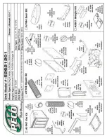
Summary of Contents for Pro 12 DFS 52621201
Page 16: ...16 ALUMINUM GRASS CONTAINER EXPLODED VIEW A0614 K1442 V1 131 6...
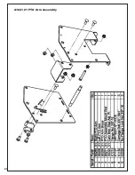
Page 22: ...22 A1841_01 PTO Arm Assembly...
Page 23: ...23 A1941_01 PTO Base Assembly Exploded Parts View...
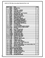
Page 24: ...24 A1941_01 PTO Base Assembly Exploded Parts List...
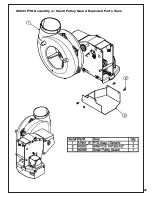
Page 25: ...25 A0623 PTO Assembly w Small Pulley Guard Exploded Parts View...
Page 26: ...26...
Page 30: ...30...
Page 31: ...31 NOTES...

