6
NOTE:
The mower deck PTO belt must be removed
from the electric clutch before continuing with the
installation. Refer to your mower owner’s manual for
instructions on PTO belt removal.
Preparation Of Mower
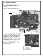
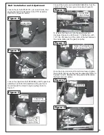
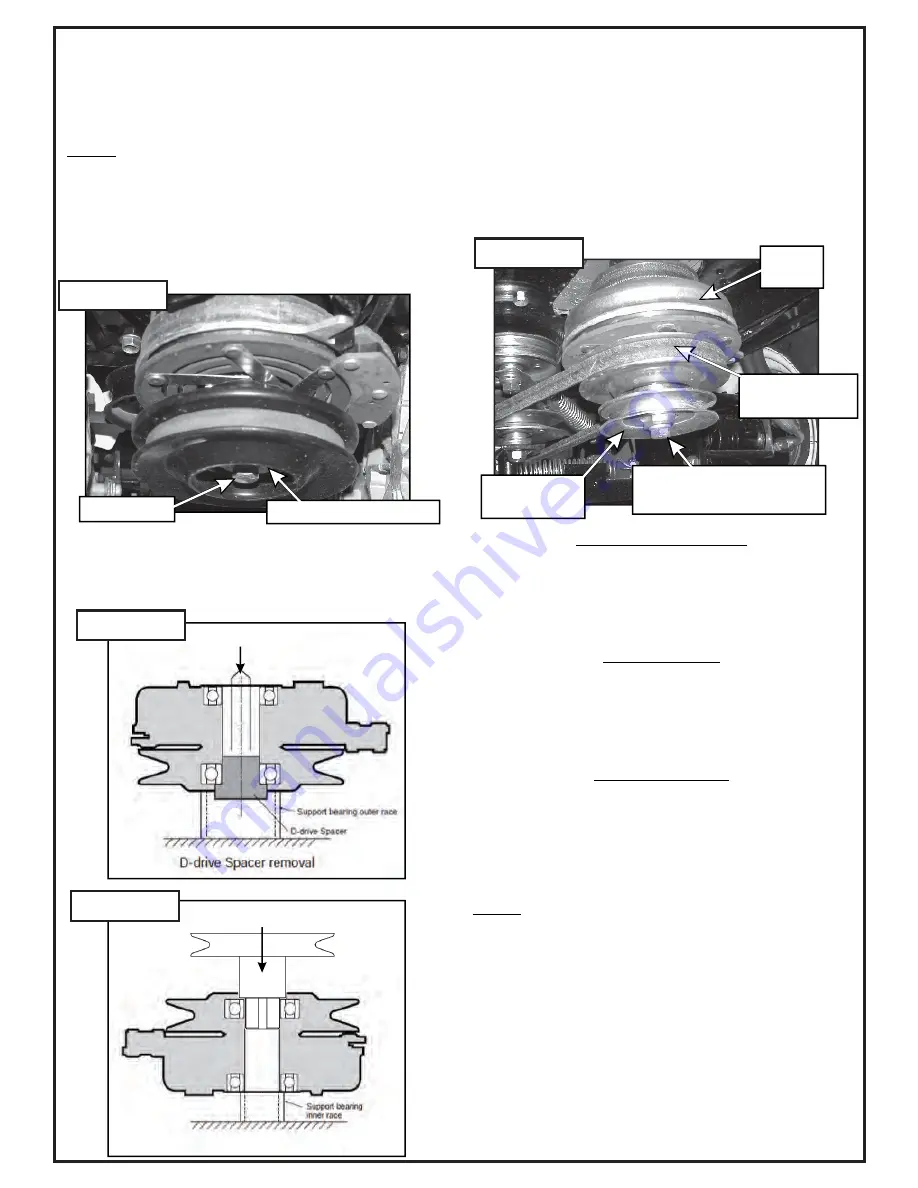
From the underside of the engine, disconnect the wiring
harness attached to the electric clutch. Remove the bolt
and electric clutch from the mower. Refer to Figure A.
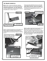
Remove the D-drive spacer using an arbor press or
equivalent. On removal, adjacent bearing OUTER race
must be supported or bearing damage may occur. Refer
to Figure B.
26 HP Briggs & Stratton
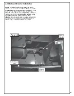
Fasten the engine pulley assembly stamped with
number 23 P#(A1175) to the electric clutch using (1)
7/16”-20 x 3-1/4” HHCS P#(K0351) and (1) 7/16” helical
spring lock washer P#(K0140). Torque the bolt to
55ft./lbs. Refer to Figure D for reference.
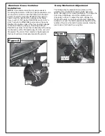
The engine pulley assembly must be installed using an
arbor press or equivalent. During installation, opposite
bearing inner race must be supported or bearing
damage may occur. Refer to Figure C.
Upon pressing the engine pulley to the clutch, replace
the completed assembly to the mower’s engine shaft to
fasten.
Fasten the engine pulley assembly stamped with
number 20 P#(A1798) to the electric clutch using (1)
7/16”-20 x 4-1/2” HHCS P#(K0427) and (1) 7/16” helical
spring lock washer P#(K0140). Torque the bolt to
55ft./lbs. Refer to Figure D for reference.
NOTE:
Replace the mower deck PTO belt removed at
the beginning of this section.
Kawasaki FX850
Kawasaki FX1000V
Fasten the engine pulley assembly stamped with
number 20 P#(A1798) to the electric clutch using (1)
7/16”-20 x 4” HHCS P#(K0359) and (1) 7/16” helical
spring lock washer P#(K0104). Torque the bolt to
55ft./lbs. Refer to Figure D for reference.
Section II - INSTALLATION FOR USE
PRESS
Remove Bolt
Remove D Drive Spacer
(1) 7/16”-20 Hex Bolt
(1) 7/16” Lock Washer
Electric
Clutch
Engine Pulley
Assembly
Replace Mower
Deck PTO Belt
PRESS
Engine Pulley Installation
Figure A
Figure B
Figure C
Figure D
Summary of Contents for Pro 12 DFS 52621201
Page 16: ...16 ALUMINUM GRASS CONTAINER EXPLODED VIEW A0614 K1442 V1 131 6...
Page 22: ...22 A1841_01 PTO Arm Assembly...
Page 23: ...23 A1941_01 PTO Base Assembly Exploded Parts View...
Page 24: ...24 A1941_01 PTO Base Assembly Exploded Parts List...
Page 25: ...25 A0623 PTO Assembly w Small Pulley Guard Exploded Parts View...
Page 26: ...26...
Page 30: ...30...
Page 31: ...31 NOTES...

