background image

MN-36956/MM-1074

  Rev 0 (01/15) • Blanket Warming Cabinet Operation & Care Manual • 2

T A B L E   O F   C O N T E N T S

Environmental Conditions .  .  .  .  .  .  .  .  .  .  .  .  .  .  .  .  .  .  .  .  .  .  .  .  .  .  .  .  .  .  .  .  .  .  .  .  .  .  .  . 1

Delivery .  .  .  .  .  .  .  .  .  .  .  .  .  .  .  .  .  .  .  .  .  .  .  .  .  .  .  .  .  .  .  .  .  .  .  .  .  .  .  .  .  .  .  .  .  .  .  .  .  .  .  .  .  . 1

Transportation Damage and Claims .  .  .  .  .  .  .  .  .  .  .  .  .  .  .  .  .  .  .  .  .  .  .  .  .  .  .  .  .  .  .  . 1

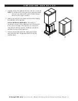
Unpacking .  .  .  .  .  .  .  .  .  .  .  .  .  .  .  .  .  .  .  .  .  .  .  .  .  .  .  .  .  .  .  .  .  .  .  .  .  .  .  .  .  .  .  .  .  .  .  .  .  .  .  . 2

Safety Procedures and Precautions .  .  .  .  .  .  .  .  .  .  .  .  .  .  .  .  .  .  .  .  .  .  .  .  .  .  .  .  .  .  .  . 3

Installation

 Preparation .  .  .  .  .  .  .  .  .  .  .  .  .  .  .  .  .  .  .  .  .  .  .  .  .  .  .  .  .  .  .  .  .  .  .  .  .  .  .  .  .  .  .  .  .  .  .  .  . 4

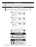
Electrical Information   .  .  .  .  .  .  .  .  .  .  .  .  .  .  .  .  .  .  .  .  .  .  .  .  .  .  .  .  .  .  .  .  .  .  .  .  .  .  .  .  .  .4

General Information   .  .  .  .  .  .  .  .  .  .  .  .  .  .  .  .  .  .  .  .  .  .  .  .  .  .  .  .  .  .  .  .  .  .  .  .  .  .  .  .  .  . 5

Dimension Drawings, Weights & Capacities

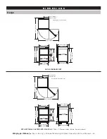
P-2012   .  .  .  .  .  .  .  .  .  .  .  .  .  .  .  .  .  .  .  .  .  .  .  .  .  .  .  .  .  .  .  .  .  .  .  .  .  .  .  .  .  .  .  .  .  .  .  .  . 6-7

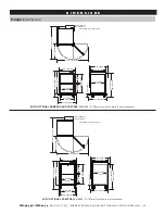
P-2022   .  .  .  .  .  .  .  .  .  .  .  .  .  .  .  .  .  .  .  .  .  .  .  .  .  .  .  .  .  .  .  .  .  .  .  .  .  .  .  .  .  .  .  .  .  .  .  .  . 8-9

P-2032   .  .  .  .  .  .  .  .  .  .  .  .  .  .  .  .  .  .  .  .  .  .  .  .  .  .  .  .  .  .  .  .  .  .  .  .  .  .  .  .  .  .  .  .  .  .  . 10-11

P-2032/PT   .  .  .  .  .  .  .  .  .  .  .  .  .  .  .  .  .  .  .  .  .  .  .  .  .  .  .  .  .  .  .  .  .  .  .  .  .  .  .  .  .  .  .  . 12-13

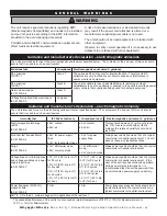
General Warnings .  .  .  .  .  .  .  .  .  .  .  .  .  .  .  .  .  .  .  .  .  .  .  .  .  .  .  .  .  .  .  .  .  .  .  .  .  .  .  .  .  .  . 14

Guidance and Manufacturer’s Declaration    .  .  .  .  .  .  .  .  .  .  .  .  .  .  .  .  .  .  .  .  . 14-15

Operating Instructions

Blanket Control Features   .  .  .  .  .  .  .  .  .  .  .  .  .  .  .  .  .  .  .  .  .  .  .  .  .  .  .  .  .  .  .  .  .  .  .  .  . 16

Operation Procedures   .  .  .  .  .  .  .  .  .  .  .  .  .  .  .  .  .  .  .  .  .  .  .  .  .  .  .  .  .  .  .  .  .  .  .  .  .  .  . 17

Care and Cleaning

Cleaning and Preventative Maintenance

Protecting Stainless Steel Surfaces  .  .  .  .  .  .  .  .  .  .  .  .  .  .  .  .  .  .  .  .  .  .  .  .  .  .  . 18

  Cleaning 

Agents  .  .  .  .  .  .  .  .  .  .  .  .  .  .  .  .  .  .  .  .  .  .  .  .  .  .  .  .  .  .  .  .  .  .  .  .  .  .  .  .  .  . 18

  Cleaning 

Materials   .  .  .  .  .  .  .  .  .  .  .  .  .  .  .  .  .  .  .  .  .  .  .  .  .  .  .  .  .  .  .  .  .  .  .  .  .  .  .  . 18

Annual Preventative Maintenance   .  .  .  .  .  .  .  .  .  .  .  .  .  .  .  .  .  .  .  .  .  .  .  .  .  .  .  . 18

Clean the Unit Regularly .  .  .  .  .  .  .  .  .  .  .  .  .  .  .  .  .  .  .  .  .  .  .  .  .  .  .  .  .  .  .  .  .  .  .  .  .  . 19

Service


Troubleshooting Guide  .  .  .  .  .  .  .  .  .  .  .  .  .  .  .  .  .  .  .  .  .  .  .  .  .  .  .  .  .  .  .  .  .  .  .  .  . 20-21

Fuse Replacement  .  .  .  .  .  .  .  .  .  .  .  .  .  .  .  .  .  .  .  .  .  .  .  .  .  .  .  .  .  .  .  .  .  .  .  .  .  .  .  .  .  . 22

Zone Heating Pad Locations   .  .  .  .  .  .  .  .  .  .  .  .  .  .  .  .  .  .  .  .  .  .  .  .  .  .  .  .  .  .  .  .  .  . 22

Options & Accessories  .  .  .  .  .  .  .  .  .  .  .  .  .  .  .  .  .  .  .  .  .  .  .  .  .  .  .  .  .  .  .  .  .  .  .  .  .  .  . 22

Full Assembly Service View  .  .  .  .  .  .  .  .  .  .  .  .  .  .  .  .  .  .  .  .  .  .  .  .  .  .  .  .  .  .  .  .  . 23-24

Electrical Chassis Service View  .  .  .  .  .  .  .  .  .  .  .  .  .  .  .  .  .  .  .  .  .  .  .  .  .  .  .  .  .  .  .  . 25

Cavity Sensor Service View  .  .  .  .  .  .  .  .  .  .  .  .  .  .  .  .  .  .  .  .  .  .  .  .  .  .  .  .  .  .  .  .  .  .  . 26

Control Interface Service View  .  .  .  .  .  .  .  .  .  .  .  .  .  .  .  .  .  .  .  .  .  .  .  .  .  .  .  .  .  .  .  .  . 27

Shelf (P-2022/P-2032) Service View   .  .  .  .  .  .  .  .  .  .  .  .  .  .  .  .  .  .  .  .  .  .  .  .  .  .  .  . 28

Wire Diagrams

   .  .  . refer to wire diagram included with the unit (under top lid)

Summary of Contents for P-2012

Page 1: ...56 MM 1074 Rev 0 01 15 P 2012 P 2022 P 2032 P 2012 Shown with optional lock solid door P 2032 Shown with optional lock and left hinged door P 2022 Shown with optional solid door casters and plate p r...

Page 2: ...eclaration 14 15 Operating Instructions Blanket Control Features 16 Operation Procedures 17 Care and Cleaning Cleaning and Preventative Maintenance Protecting Stainless Steel Surfaces 18 Cleaning Agen...

Page 3: ...ommended environmental temperature range is 15 C to 32 C 60 F to 90 F Recommended relative humidity is above 20 non condensation E N V I R O N M E N T A L C O N D I T I O N S All Pedigo Products Inc e...

Page 4: ...tions in this manual carefully before initiating the installation of this appliance DO NOT DISCARD THIS MANUAL This manual is considered to be part of the appliance and is to be provided to the owner...

Page 5: ...gnal words and symbols may be used throughout this manual NOT E For equipment delivered for use in any location regulated by the following directive DO NOT DISPOSE OF ELECTRICAL OR ELECTRONIC EQUIPMEN...

Page 6: ...uipment BS 1363 Plug UK only CEE 7 7 220 230V Plug IPX 0 Other international plugs are available Contact factory for more information Domestic ground shipping information Contact factory for export we...

Page 7: ...V A C 60 Hz 1 ph 0 6 kW 5 0 Amps Safety Class I Equipment No Applied Parts Mode of Operation Continuous NEMA 5 15P 15A 125V Plug Hospital Grade IPX 0 220 V A C 60 Hz 1 ph 0 6 kW 2 7 Amps Type B Equipm...

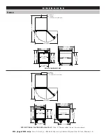
Page 8: ...1 83m est 18 0 457mm 9 1 232mm IEC Cord Inlet 42 2 1071mm 36 0 914mm 26 2 666mm with optional casters with plate 5017544 3 76mm casters 2 rigid 2 swivel w brake D I M E N S I O N S 18 5 470mm 21 9 557...

Page 9: ...length 6 ft 1 83m est 22 8 579mm IEC Cord Inlet P 2012 continued with optional bumpers and casters 5017548 3 76mm casters 2 rigid 2 swivel w brake D I M E N S I O N S 18 5 470mm 25 5 647mm 21 2 538mm...

Page 10: ...rd Inlet 18 0 457mm 42 3 1073mm Cord length 6 ft 1 83m est 36 0 914mm 28 8 730mm IEC Cord Inlet 26 3 669mm 9 3 235mm IEC Cord Inlet 18 0 457mm 22 0 559mm 18 5 470mm CAVITY 20 6 523mm 15 5 394mm CAVITY...

Page 11: ...7mm 42 1 1070mm 36 3 921mm Cord length 6 ft 1 83m est 28 8 730mm IEC Cord Inlet 26 5 674mm 22 0 559mm 18 5 470mm CAVITY 20 6 523mm 26 3 669mm 15 5 394mm CAVITY 14 5 369mm INSERT 18 5 470mm 21 1 537mm...

Page 12: ...rd Inlet 23 5 597mm 50 0 1270mm Cord length 6 ft 1 83m est 47 0 1193mm 35 6 903mm IEC Cord Inlet 28 6 726mm 12 0 305mm IEC Cord Inlet 23 5 597mm 21 0 532mm CAVITY 22 8 578mm 24 3 616mm 34 2 870mm 35 5...

Page 13: ...4 1229mm Cord length 6 ft 1 83m est 35 6 903mm IEC Cord Inlet 24 3 616mm 28 8 732mm 21 0 532mm CAVITY 25 7 654mm 24 3 616mm 34 2 870mm 40 7 1033mm 21 0 533mm CAVITY 19 9 506mm INSERT 24 0 610mm 28 1...

Page 14: ...2 336mm INSERT 21 4 543mm CAVITY 27 1 688mm 24 4 619mm Cord length 6 ft 1 83m est 23 5 597mm 70 0 1779mm 23 5 70 0 1779mm 27 2 691mm 35 9 911mm 19 9 506mm 128mm 21 4 543mm CAVITY 12 2 309mm IEC Cord...

Page 15: ...779mm 28 1 715mm CAVITY 13 1 333mm INSERT 13 2 336mm INSERT 24 4 619mm 27 2 691mm 35 9 911mm 39 3 998mm 5 0 128mm 19 9 506mm 23 5 597mm 70 0 1779mm 23 5 597mm 70 0 1779mm 21 4 543mm CAVITY 12 2 309mm...

Page 16: ...3 3 Complies Guidance and manufacturer s declaration electromagnetic immunity The unit is intended for use in the electromagnetic environment specified below The customer or the end user of this unit...

Page 17: ...accuracy To assess the electromagnetic environment due to fixed RF transmitters an electromagnetic site survey should be considered If the measured field strength in the location in which the unit is...

Page 18: ...ntrol senses a temperature of 71 C 160 F or higher The alarm can be muted by pressing the ON OFF button ERROR ACKNOWLEDGEMENT To clear or acknowledge an error press the ON OFF button Press the ON OFF...

Page 19: ...ARROW keys to change the value shown in the display The temperature set point range is 32 71 C 90 160 F 5 LOAD THE CHAMBER WITH DRY COTTON BLANKETS DO NOT WARM ITEMS CONTAINING PLASTIC RUBBER OR METAL...

Page 20: ...grain of surface metal to avoid surface scratches Never use wire brushes metal scouring pads or scrapers to remove residue 1 Ensure that the correct Operation and Care Manual is available to all users...

Page 21: ...ners or cleaners containing quaternary salts Never use hydrochloric acid muriatic acid on surfaces 3 Clean the interior metal surfaces of the cabinet with a damp cloth and any mild commercial detergen...

Page 22: ...should test the heater pad s Turn unit OFF and unplug it from AC power Use Ohm meter to measure resistance between L Line N Neutral leads of a cold heater pad The Ohm readings shall be 120V 72 Ohm 10...

Page 23: ...Error Fluid Warmers Only Temperature of cavity sensors 1 and 2 differ by more than 1 7 C 3 F Remove product and allow unit to cool down Verify that product sensor is clean and operating correctly Pre...

Page 24: ...tory contact factory contact factory contact factory STACKING HARDWARE P 2012 or P 2022 over P 2012 or P 2022 5017272 5017272 P 2012 or P 2022 triple stacked 5017539 5017539 F U S E R E P L A C E M E...

Page 25: ...I C E Always include both model and serial numbers in your correspondence regarding the unit Model _____________________________________ Serial Number _____________________________________ SERIAL NUM...

Page 26: ...7998 1 P 2022 5017999 1 P 2032 5018000 1 12 PLATE LOWER HINGE RIGHT HINGED DOOR 5015523 1 LEFT HINGED DOOR 5018611 1 13 SCREW M8 x 1 25 x 20mm HEX FLG SC 27406 3 14 BOTTOM COVER P 2012 P 2022 1014270...

Page 27: ...Model _____________________________________ Serial Number _____________________________________ SERIAL NUMBER IS REQUIRED FOR ALL INQUIRIES ELECTRICAL CHASSIS 1 2 3 5 6 4 ITEM DESCRIPTION PART QTY 1 C...

Page 28: ...de both model and serial numbers in your correspondence regarding the unit Model _____________________________________ Serial Number _____________________________________ SERIAL NUMBER IS REQUIRED FOR...

Page 29: ...12 P 2022 shown 2 3 1 4 5 6 7 8 12 11 10 9 ITEM DESCRIPTION PART QTY 1 OVERLAY P 2012 PE 37112 1 P 2022 PE 37111 1 P 2032 PE 37110 1 2 INTERFACE ASSEMBLY 18 5 P 2012 5018715 1 P 2022 5018717 1 INTERFA...

Page 30: ...___ Serial Number _____________________________________ SERIAL NUMBER IS REQUIRED FOR ALL INQUIRIES SHELF P 2022 P 2032 only 36 2 3 1 4 5 6 7 8 ITEM DESCRIPTION PART QTY 1 PANEL TOP 1014609 1 2 INSULA...

Page 31: ...MN 36956 MM 1074 Rev 0 01 15 Blanket Warming Cabinet Operation Care Manual 29 Refer to wire diagram included with the unit...

Page 32: ...15 months from the shipping date whichever occurs first The original parts warranty on all other parts remains in effect three 3 years from installation of appliance or thirty nine 39 months from the...

Reviews: