background image

21

MM-1065 (MN-29614) • Rev 4 • 06/16 • Pedigo Fluid Warmer

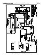
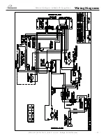
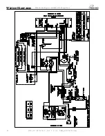
Wiring Diagrams

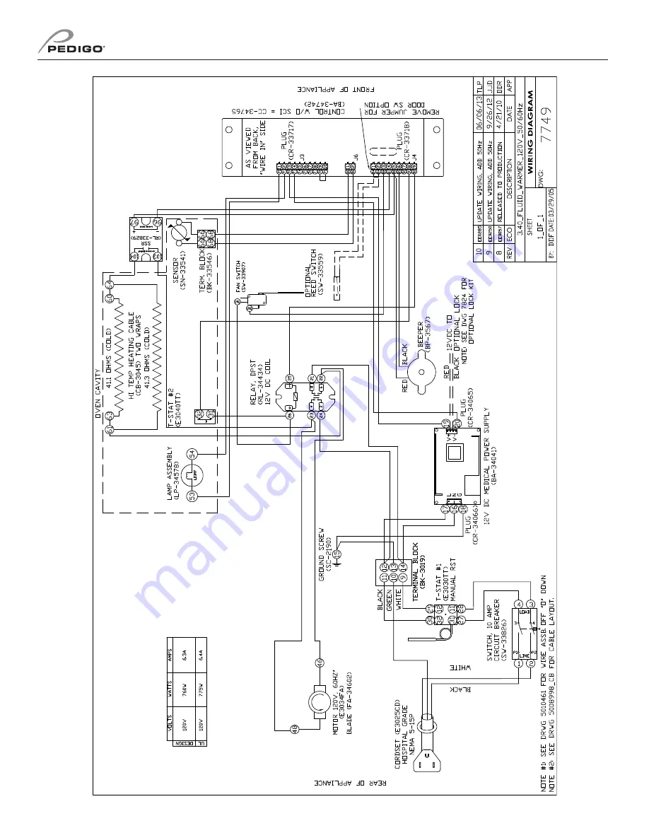
Refer to wire diagram included with the appliance.

Summary of Contents for P-2110

Page 1: ...manual operation care P 2110 P 2120 P 2130 120V MM 1065 MN 29614 Rev 4 06 16 Printed in the U S A P 2110 P 2120 P 2130 Fluid Warmers...

Page 2: ...4 Dimensions 5 Electrical Information 8 Operation Instructions 9 Cleaning and Preventative Maintenance 12 Troubleshooting 14 Service 16 Wiring Diagrams Refer to the wire diagram included with the app...

Page 3: ...tions Receipt of Appliance All Pedigo Products Inc appliances are sold F O B shipping point and when accepted by the carrier such shipments become the property of the consignee Should damage occur in...

Page 4: ...ndicated in this guide to use and clean the appliance is considered inappropriate and may cause damage injury or fatal accidents in addition to invalidating the guarantee and relieving the manufacture...

Page 5: ...nces with other municipal waste Fluid warmers are only intended for warming medical solutions for irrigation and injection prior to their use Please refer to the labeling of the manufacturer of the pr...

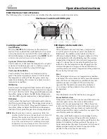
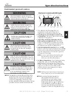
Page 6: ...dicators The electronic control can be set to operate in fahrenheit or celsius After a power failure the appliance will remember its programming and begin to operate as before The on off indicator wil...

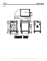
Page 7: ...P 2110 38 9 987mm 22 8 580mm 19 4 493mm 13 8 351mm CAVITY 1 2 31mm 13 1 333mm CAVITY 16 2 410 4mm 19 0 475mm ELECTRICAL CONNECTION 21 5 547mm CAVITY 28 0 711mm 17 5 445mm 11 9 302mm 43 0 1092mm 17 9 4...

Page 8: ...Dimensions P 2120 33 4 849mm 27 0 685mm 20 0 508mm CAVITY 14 1 359mm CAVITY 21 6 549mm CAVITY 1 5 37mm Electrical Connection 45 0 1143mm 28 5 725mm 24 3 613mm 8 7 221mm 17 4 441mm 20 7 525mm 7 7 195m...

Page 9: ...2 8 1341mm 35 0 890mm 28 0 731mm 11 0 280mm 2 20 55 6mm OFF ON 30 10 764mm 25 10 638mm 5 5 140mm 18 9 480mm Cavity 25 2 639mm 26 9 684mm Cavity 35 1 892mm 40 8 1036mm 54 0 1372mm 33 876 860 5mm 22 3 5...

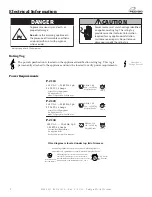
Page 10: ...t P 2110 Safety Class I Equipment Protective Earth Ground Symbol Medical Equipment classified by Underwriters Laboratories with Respect to Electrical Shock Fire and Mechanical Hazards only in Accordan...

Page 11: ...en the electronic control senses a temperature 6 C 10 F greater than the set point this indicator illuminates the audible alarm sounds and the on off button indicator blinks The green indicator of the...

Page 12: ...ve 5 seconds Press again to turn the sound on or off Electronic Control Lock The electronic control can be locked so that no changes can be made to the temperature set point or the mode selection Pres...

Page 13: ...tton to select the irrigation fluids mode or the INJ button to choose the injection fluids mode The last set point temperature for that mode of operation will appear in the display 5 Set desired tempe...

Page 14: ...and make certain to scrub with the visible grain of surface metal to avoid surface scratches Cleaning the Appliance 1 Disconnect the appliance from the power source 2 Remove all detachable items such...

Page 15: ...Check the condition of the stacking hardware if applicable making sure the mounting bolts and the hardware are secure Preventative Maintenance Checklist Weekly Checklist Inspect the condition of the p...

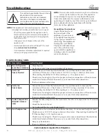
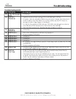
Page 16: ...be defective If error continues call service E 50 Temp Measurement Error Call service E 60 Real Time Clock Error Appliance may have been unplugged for an extended period of time To resolve turn circui...

Page 17: ...tegrity Check for proper and secure connections at the electronic control and terminal block If necessary re secure the faulty connections If error continues call service E 11 Cavity Air Sensor Open D...

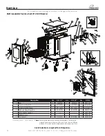
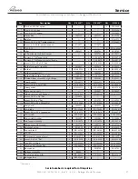
Page 18: ...3 Strain relief bushing 1 BU 34836 1 BU 34836 1 BU 34836 4 Cordset hospital grade 1 E3025CD 1 E3025CD 1 E3025CD 5 Plate motor mount 1 1004300 6 Motor spacer 1 1004303 7 Fan motor 1 E3034FA 1 E3034FA 1...

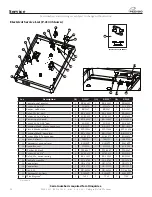
Page 19: ...010808 1 5001253 25 Door handle 1 HD 24171 1 HD 24171 1 HD 24171 26 Screw 10 32 x 1 1 2 flat 4 SC 35259 4 SC 35259 4 SC 35259 27 Door gasket 1 E2132GS 1 GS 22950 1 GS 23794 28 Plate cover vent 2 10108...

Page 20: ...BA 34041 1 BA 34041 7 Screw 6 32 x 1 1 4 pan 2 SC 2365 2 SC 2365 2 SC 2365 8 Terminal block 3 form compress 1 BK 3019 1 BK 3019 1 BK 3019 9 Circuit breaker switch 1 SW 33826 1 SW 33826 1 SW 33858 10 T...

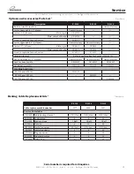
Page 21: ...el w brake CS 2026 CS 2026 Screw 4 required for each caster SC 2351 SC 2351 Combination lock Refer to combination lock manual MN 28753 Leg kit upgrade kit 6 152mm Contact factory Contact factory Conta...

Page 22: ...20 MM 1065 MN 29614 Rev 4 06 16 Pedigo Fluid Warmer Wiring Diagrams Refer to wire diagram included with the appliance...

Page 23: ...21 MM 1065 MN 29614 Rev 4 06 16 Pedigo Fluid Warmer Wiring Diagrams Refer to wire diagram included with the appliance...

Page 24: ...22 MM 1065 MN 29614 Rev 4 06 16 Pedigo Fluid Warmer Wiring Diagrams Refer to wire diagram included with the appliance...

Page 25: ...oval of any parts including legs or addition of any parts 6 Collateral or incidental damage as a direct result of servicing equipment built into a wall structure is not covered under warranty It is th...

Reviews: