20
| ENGLISH
DESCRIPTION OF THE PRODUCT
DG PED
is an automatic pressurisation system with an in-
verter which integrates: built-in high efficiency self-priming
pump, a accumulator tank, pressure and flow rate sensors, a
non-return valve.
DG PED
is a compact autonomous quiet and high perfor-
mance pumping system.
A sophisticated electronic control inverter controls the entire
system in an intelligent and intuitive manner:
• it maintains the pressure of the installation constant by
regulating the velocity of the pump in accordance with the
water required;
• it controls the hydraulic and electric operating parameters
and protects the pump from abnormalities;
• it can be equipped with an expansion card that makes it
possible to work in parallel with other DG PED in the pump-
ing groups and to manage input and output signals;
• it adapts to every type of pressurisation system, including
existing ones. Where the regulations permit it the system is
suitable for use with the water supply network. In this case
insert a non-return valve upstream;
• it limits the starting and operating currents in order to pro-
vide a greater saving of energy.
In the applications in parallel the inverter MASTER and the
inverter SLAVE, controlled by the MASTER, stand out.
The MASTER receives the parameter programming details,
controls the functional data, and activates and deactivates
the SLAVES as necessary.
If the MASTER is switched off, the SLAVES return to being au-
tonomous and continue to work independently.
When it works in a parallel configuration with other inverters,
DG PED is able to manage the alternation of the starts in order
to harmonise the use of the pumps.
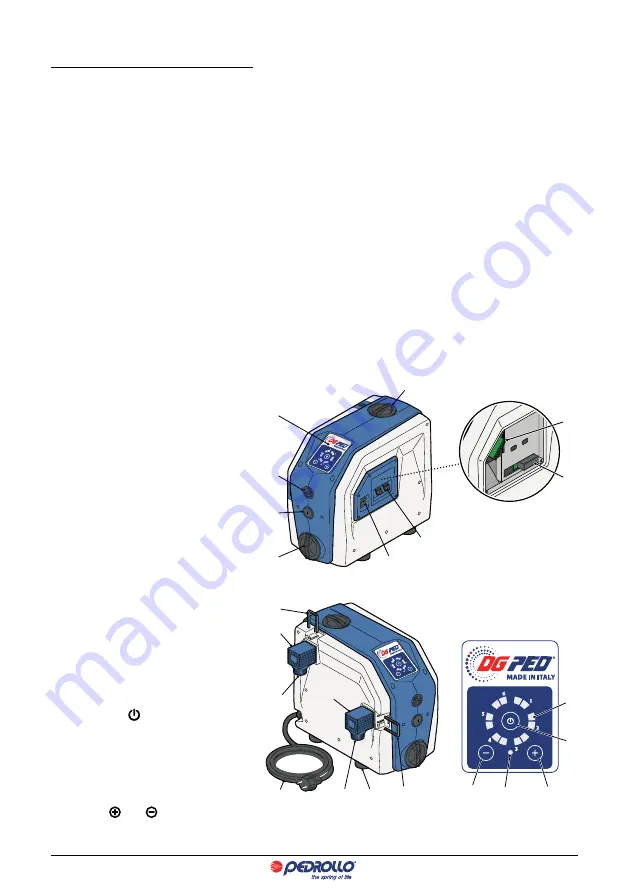
LIST OF PARTS
1. Bipolar general switch I/O
2. Cable hole signals (INPUT/OUTPUT)
3. Control
Panel
4. Filling
plug
5. Expansion vase plug
6. Vent
plug
7. Drain
plug
8. Expansion
card
9. Fuse 12.5 A (rapid intervention)
10. Connector locking bandwidth
11. Adjustable elbow joint, with OR
12. Discharge outlet
13. Suction port
14. Anti-vibration levelling feet
15. Electricity cable
CONTROL PANEL
16. On/off switch
17. Green coloured LED indicators that indicate:
– pump working;
– working pressure;
– alarms
18. Green or red LED indicators
19. Switches anda for changing readings
16
19
18
17
19
3
5
6
7
4
2
1
10
11
9
12
14
13
10
15
8
9


