background image

3 of 6

ISSUED: 12-27-10  SHEET #: 120-9100-2  06-13-11

Visit the Peerless Web Site at www.peerlessmounts.com

For customer care call 1-800-865-2112

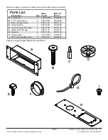
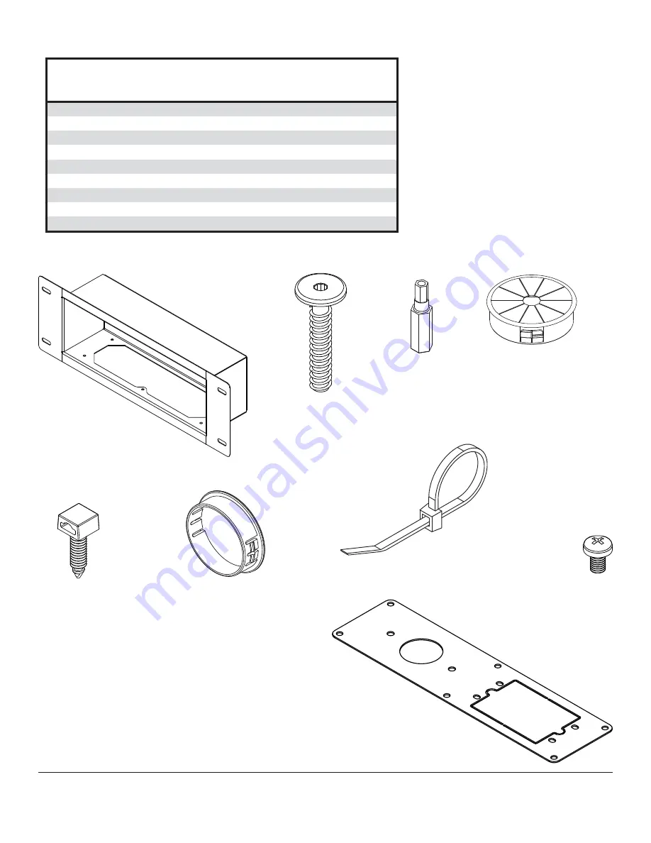
Before you begin, make sure all parts shown are included with your product.

E

D

A

F

B

G

I

H

C

Parts may appear slightly different than illustrated. 

IBA3

IBA3-W

Description

Qty.

Part #

Part #

A

in-wall box

1

120-P1186

120-2186

B

1-1/2" wood screw

4

500-1090

500-4090

C

4mm security driver

1

560-1133

560-1133

D

cable bushing

1

590-1295

590-2295

E

cable management clips

2

590-1166

590-1166

F

plastic finishing cap

1

590-1123

590-2123

G

cable tie

2

590-1168

590-1168

H

access plate

1

120-P1187

120-2187

I

M5 x 6mm phillips screw

5

520-1023

520-2214

Parts List

Summary of Contents for IBA3-W

Page 1: ...W Installation and Assembly Recessed Cable Management and Power Storage Accessory Box ISSUED 12 27 10 SHEET 120 9100 2 06 13 11 2300 White Oak Circle Aurora Il 60502 800 865 2112 Fax 800 359 6500 www peerlessmounts com ...

Page 2: ...ached hardware and components If mounting to wood wall studs make sure that mounting screws are anchored into the center of the studs Use of an edge to edge stud finder is highly recommended Tighten screws firmly but do not overtighten Overtightening can damage the items greatly reducing their holding power This product is intended for indoor use only Use of this product outdoors could lead to pro...

Page 3: ...ppear slightly different than illustrated IBA3 IBA3 W Description Qty Part Part A in wall box 1 120 P1186 120 2186 B 1 1 2 wood screw 4 500 1090 500 4090 C 4mm security driver 1 560 1133 560 1133 D cable bushing 1 590 1295 590 2295 E cable management clips 2 590 1166 590 1166 F plastic finishing cap 1 590 1123 590 2123 G cable tie 2 590 1168 590 1168 H access plate 1 120 P1187 120 2187 I M5 x 6mm ...

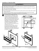
Page 4: ... the mounting holes are on stud centerlines Drill four 3 16 5mm dia holes 1 1 2 38mm deep Make sure in wall box is level and secure it using four wood screws B as shown in fig 1 2 Installation to Wood Stud Wall 1 Installer must verify that the supporting surface will safely support the combined load of the equipment and all attached hardware and components Tighten wood screws so that in wall box i...

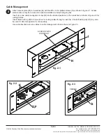
Page 5: ...all box A with five M5 x 6mm phillips screws I as shown in figure 2 1 Access plate knockout may be removed for optional installation of electrical gang box Insert up to two cable management clips E into the desired positions in the in wall box as shown in figure 2 2 for routing cables Insert cable bushing D into in wall box for routing cables through in wall box Plastic finishing cap F may also be...

Page 6: ...erson who is not authorized for such service or repairs by Peerless b the failure to utilize proper packing when returning the product c incorrect installation or the failure to follow Peerless instructions or warnings when installing using or storing the product or d misuse or accident in transit or otherwise including in cases of third party actions and force majeure In no event shall Peerless b...

Reviews: