4 of 6
ISSUED: 12-27-10 SHEET #: 120-9100-2 06-13-11
Visit the Peerless Web Site at www.peerlessmounts.com
For customer care call 1-800-865-2112
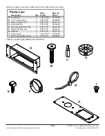
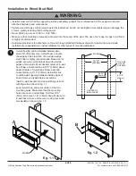
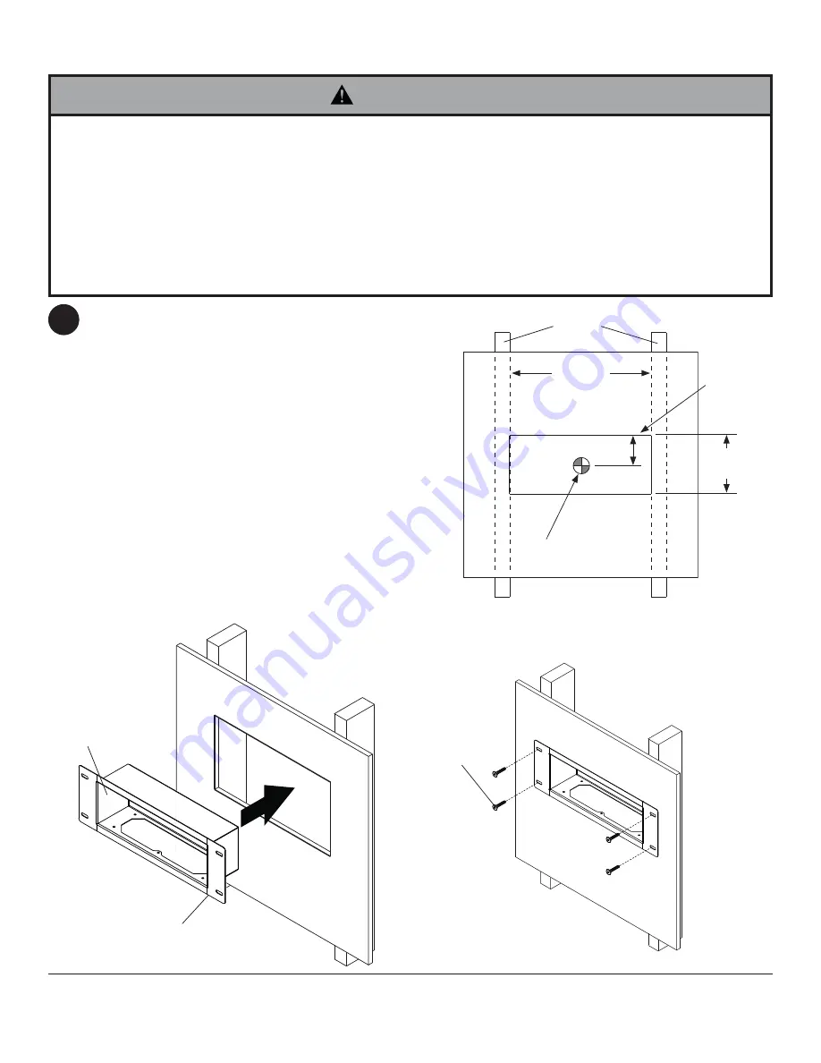
In-wall box (
A
) can be installed between two
studs 16" off center. Use a stud fi nder to locate
the edges of the stud. Use of an edge-to-edge
stud fi nder is highly recommended. Based on its
edges, draw two vertical lines down the inside
edges of two stud’s. Mark desired center of in-wall
box. Draw a horizontal line 2-5/16" (59mm) above
desired center of in-wall box. Draw a second
horizontal line 4-7/16" (114mm) below fi rst line
to outline wall opening between inside edges of
studs. Remove drywall inside cut outline.
Insert in-wall box (
A
) into wall until fl ange is fl ush
with drywall as shown in fi g. 1.1.
Level in-wall box, and mark center of the four
mounting holes. Make sure that the mounting
holes are on stud centerlines. Drill four 3/16"
(5mm) dia. holes 1-1/2" (38mm) deep. Make sure
in-wall box is level, and secure it using four wood
screws (
B
) as shown in fi g. 1.2.
Installation to Wood Stud Wall
1
• Installer must verify that the supporting surface will safely support the combined load of the equipment and all
attached hardware and components.
• Tighten wood screws so that in-wall box is fi rmly attached, but do not overtighten. Overtightening can damage the
screws, greatly reducing their holding power.
• Never tighten in excess of 80 in. • lb (9 N.M.).
• Make sure that mounting screws are anchored into the center of the stud. The use of an "edge to edge" stud fi nder
is highly recommended.
• Hardware provided is for attachment of mount through standard thickness drywall or plaster into wood studs.
Installers are responsible to provide hardware for other types of mounting situations.
WARNING
4-7/16"
(114mm)
13-1/8"
(333mm)
fi g. 1.1
STUDS
A
FLANGE
TOP LINE
OF CUT
OUTLINE
CENTER OF
IN-WALL BOX
2-5/16"
(59mm)
B
fi g. 1.2


