5 of 6
ISSUED: 12-27-10 SHEET #: 120-9100-2 06-13-11
Visit the Peerless Web Site at www.peerlessmounts.com
For customer care call 1-800-865-2112
E
H
I
D,F
G
CABLES
fi g. 2.2
fi g. 2.3
fi g. 2.1
© 2011, Peerless Industries, Inc. All rights reserved.
All other brand and product names are trademarks or registered trademarks of their respective owners.
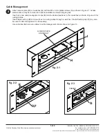
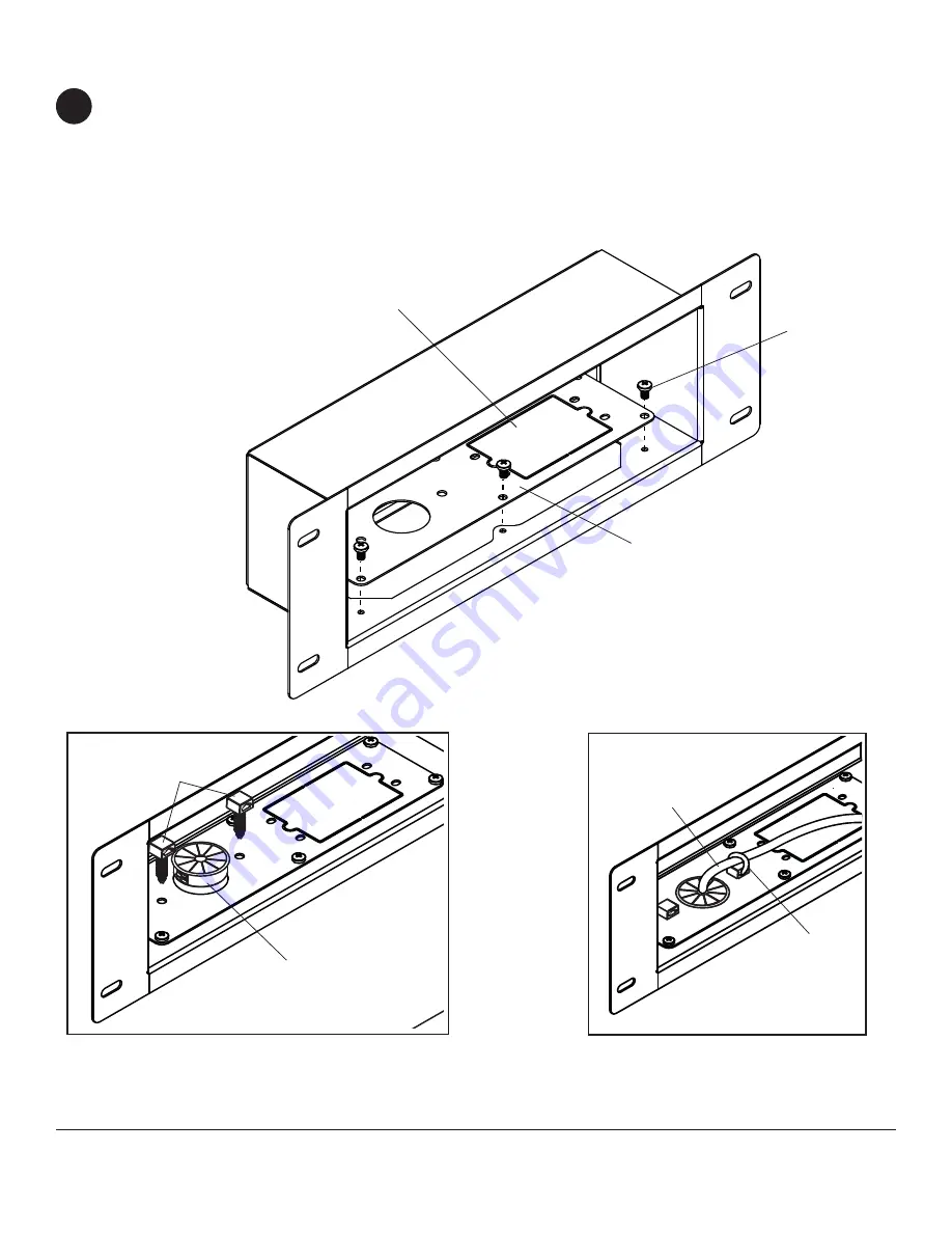
Attach access plate (
H
) to in-wall box (
A
) with fi ve M5 x 6mm phillips screws (
I
) as shown in fi gure 2.1. Access
plate knockout may be removed for optional installation of electrical gang box.
Insert up to two cable management clips (
E
) into the desired positions in the in-wall box as shown in fi gure 2.2 for
routing cables.
Insert cable bushing (
D
) into in-wall box for routing cables through in-wall box. Plastic fi nishing cap (
F
) may also
be used if cable management is unnecessary.
Use cable ties (
G
) to secure cables to cable management clips as shown in fi gure 2.3.
Cable Management
2
ACCESS PLATE
KNOCKOUT


