background image

5 of 18

ISSUED: 02-05-09   SHEET #: 202-9338-1

D

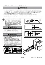
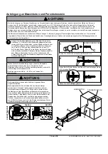
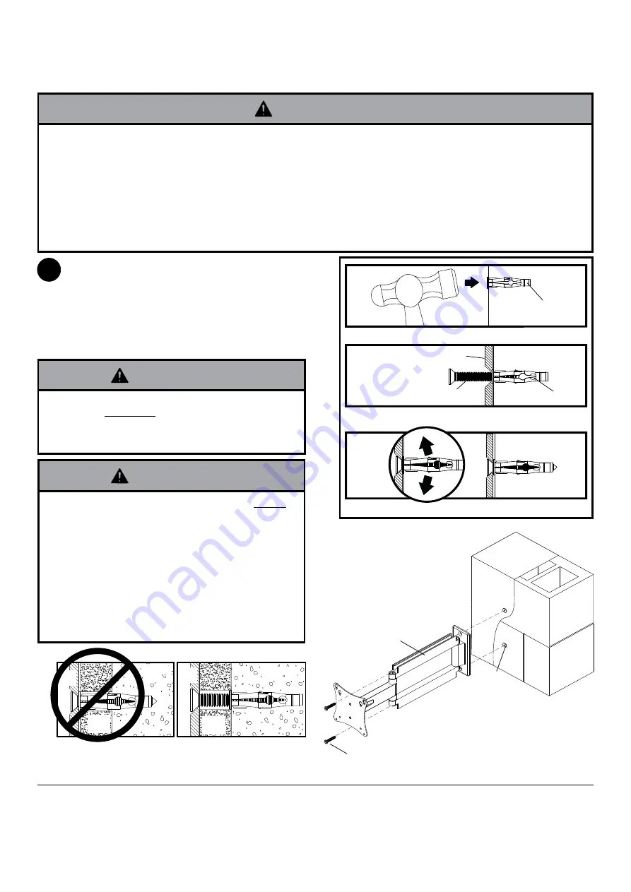
Installation to Solid Concrete and Cinder Block

Remove cord covers from wall arm assembly (

A

) as 

shown in figure 1.1 on page 4. Level and use wall 
plate as template to mark center of holes. Drill two 
5/16" (8 mm) dia. hole to a minimum depth of 2.5"  
(64 mm). Insert anchors (

C

) in holes flush with wall. 

Place wall arm (

A

) over anchor and secure with 

wood screw (

D

). Make sure wall arm is level, and 

tighten all fasteners.

A

C

1

•  When installing Peerless wall mounts on cinder block, verify that you have a minimum of 1-3/8" (35 mm) of actual 

concrete thickness in the hole to be used for the concrete anchors. Do not drill into mortar joints! Be sure to mount 
in a solid part of the block, generally 1" (25 mm) minimum from the side of the block. Cinder block must meet ASTM 
C-90 specifications. It is suggested that a standard electric drill on slow setting is used to drill the hole instead of a 
hammer drill to avoid breaking out the back of the hole when entering a void or cavity.

•  Concrete must be 2000 psi density minimum. Lighter density concrete may not hold concrete anchor.

•  Make sure that the wall will safely support four times the combined load of the equipment and all attached hardware 

and components.

WARNING

•  Tighten screws so that wall plate is firmly attached, 

but do not overtighten. Overtightening can damage 
screws, greatly reducing their holding power.

•  Never tighten in excess of 80 in. • lb (9 N.M.).

WARNING

•  Always attach concrete expansion anchors directly 

to load-bearing concrete.

•  Never attach concrete expansion anchors to 

concrete covered with plaster, drywall, or other 
finishing material. If mounting to concrete surfaces 
covered with a finishing surface is unavoidable, 
the finishing surface must be counterbored as 
shown below. Be sure concrete anchors do not 
pull away from concrete when tightening screws. If 
plaster/drywall is thicker than 5/8" (16 mm), custom 
fasteners must be supplied by installer.

WARNING

CUT

A

W

A

Y

 VIEW

INCORRECT

CORRECT

wall 

plate

wall 

plate

plaster/
dry wall

plaster/
dry wall

concrete

concrete

1

3

2

C

Drill holes and insert anchors (

C

).

Place plate (

A

) over anchors (

C

) and secure with screws (

D

).

Tighten all fasteners.

A

C

D

concrete 
surface

Summary of Contents for D-LA-100

Page 1: ...V150 BK SWV150 SI Features Fits 10 26 25 66 cm LCD screens Pivots and articulates in all directions even around corners and cabinets Frees up space by folding at against the wall Keeps electronic wire...

Page 2: ...exceed the Maximum Load Capacity See page one If mounting to wood wall studs make sure that mounting screws are anchored into the center of the studs Use of an edge to edge stud nder is highly recomm...

Page 3: ...wood screw 2 520 1202 520 2165 E cord management clip 2 590 1264 590 2164 F M4 x 12 mm phillips screw 4 504 9013 504 2013 G M4 x 20 mm phillips screw 4 504 9020 504 2014 H retaining spacer 4 590 5005...

Page 4: ...p 2 on page 6 A Installation to Wood Stud Wall A CORD COVERS g 1 1 g 1 2 1 Installer must verify that the supporting surface will safely support the combined load of the equipment and all attached har...

Page 5: ...or cavity Concrete must be 2000 psi density minimum Lighter density concrete may not hold concrete anchor Make sure that the wall will safely support four times the combined load of the equipment and...

Page 6: ...three complete turns in the screen inserts or if screws bottom out and bracket is still not tightly secured damage may occur to screen or product may fail WARNING 1 4 FOR VESA 75 MOUNTING PATTERN FOR...

Page 7: ...s shown in gure 5 1 NOTE If hole pattern is in a pocket insert two M4 x 20 mm screws G with two retaining spacers H into top two holes of screen 4 6 5 Attaching Front Plate to Screen Using VESA 200 x...

Page 8: ...by sliding cord covers onto mount Screen may have to be moved for better access for sliding on the cord covers CORD COVERS Route cords through center of cord management clip E Next attach cord manage...

Page 9: ...if factory torque settings are adjusted If more or less tension is desired in tilt mechanism remove snap caps as shown in detail 2 Insert a at head screw driver into slot and pry cap away from tilt m...

Page 10: ...I Merkmale F r LCD Bildschirme von 10 26 Zoll 25 66 cm Schwenkbar und durch gelenkige Lagerung in alle Richtungen bewegbar selbst um Ecken und Schr nke Flach an die Wand klappbare Ausf hrung spart Pla...

Page 11: ...en Sie immer eine zus tzliche Person heran oder verwenden Sie mechanische Hebeger te um Ger te sicher zu heben und zu positionieren Ziehen Sie die Schrauben fest an ohne sie zu berdrehen Durch berdreh...

Page 12: ...520 1202 520 2165 E Kabelklemme 2 590 1264 590 2164 F M4 x 12 mm Schrauben 4 504 9013 504 2013 G M4 x 20 mm Schrauben 4 504 9020 504 2014 H Abstandhaltern 4 590 5005 590 5003 I 5 mm Inbusschl ssel 1...

Page 13: ...SEITE 15 FORT A Anbringung an W nden mit einer Holzst nderreihe A KABELABDECKUNG 1 Bei der Anbringung muss darauf geachtet werden dass die Wand die kombinierte Last von Bildschirm und allen Befestigu...

Page 14: ...etondruckfestigkeit muss mindestens 2000 psi betragen In Beton mit geringerer Druckfestigkeit kann der Betond bel u U nicht halten Vergewissern Sie sich dass die Wand das Vierfache des Gesamtgewichts...

Page 15: ...oder G durch das untere Loch der Adapterplatte siehe Abbildung 3 1 FAHREN SIE MIT SCHRITT 7 AUF SEITE 18 FORT F oder G ADAPTER PLATTE 3 Unter Verwendung der Montagemuster VESA 75 und 100 mm Sind die...

Page 16: ...Wenn sich das Lochmuster in einer Vertiefung be ndet bringen Sie zwei M4 x 20 mm Schrauben G mit zwei Abstandhaltern H in den beiden oberen L chern des Bildschirms an 4 6 5 Unter Verwendung der Monta...

Page 17: ...hieben Um die Kabelabdeckung besser hineinschieben zu k nnen m ssen Sie eventuell den Bildschirm wegbewegen F hren Sie die Kabel durch die Mitte der Kabelf hrungsklemme E Befestigen Sie dann die Kabel...

Page 18: ...chstens eine halbe Umdrehung anziehen oder lockern Zum Einstellen der Querneigung m ssen Sie einfach die 10 31 Nylock Mutter anziehen oder lockern WAHLFREI ABDECKKAPPE INBUSSCHRAUBE INBUSSCHRAUBE 10...

Reviews: