background image

7 of 24

ISSUED: 08-09-10   SHEET #: 061-9059-4  10-18-10

© 2010, Peerless Industries, Inc. All rights reserved. 

All other brand and product names are trademarks or registered trademarks of their respective owners.

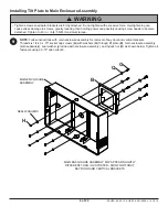
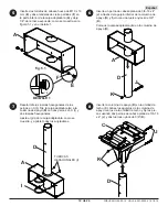
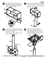
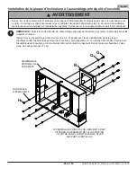
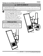
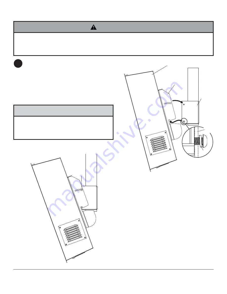
Hook tilt plate (

B

) onto bottom socket screws 

threaded into adapter box (

A

) and select desired 

tilt angle (0° to 20°) as shown in fi gure 10.1. 

NOTE:

 Be sure split lock washer (

F

) is on outside 

of tilt plate as shown in detail 2.

Insert two M10 x 16 mm socket screws (

E

) and 

two split lock washers (

F

) through tilt plate (

B

) and 

into top of adapter box (

A

) as shown in fi gure 10.2. 

Tighten all fasteners using 6 mm allen wrench.

Mounting Main Enclosure Assembly

10

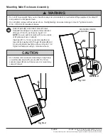
•  Do not lift more weight than you can handle. Always use an assistant or mechanical lifting equipment to safely lift 

and position the fl at panel screen.

•  Do not tighten screws with excessive force. Overtightening can cause damage to mount. Tighten screws to 

40 in. • lb (4.5 N.M.) maximum torque.

  WARNING

•  Do not allow main enclosure assembly to hang freely 

on wall box (

A

) when all four sets of M10 x 16 mm 

socket screws (

E

) are not fully secured or mount may 

come off of wall.

CAUTION

fi g 10.1

fi g 10.2

B

E

MAIN ENCLOSURE 
ASSEMBLY

DETAIL 2

F

A

B

Summary of Contents for FPECMI-01

Page 1: ...ess Outdoor Enclosures only Installation and Assembly I Beam Mount for Peerless Outdoor Enclosures Models FPECMI 01 FPECMI 02 FPECMI 03 FPECMI 04 Max Load Capacity 400 lb 181 kg ISSUED 08 09 10 SHEET...

Page 2: ...h the enclosure extension tube and hardware must be inspected at least once a year and immediately following any time winds exceed 90 mph A qualified installer or inspector must check for signs of rus...

Page 3: ...0 5001 G 1 4 20 x 3 4 socket cap screw 6 520 5034 H 1 4 20 nylock nut 6 530 5007 I u bolt with hex nuts 2 520 5037 J carriage bolt 3 520 5039 K 3 8 16 nylock nut 3 530 5004 L ceiling clamp 2 061 7357...

Page 4: ...bolts M of right clamp and left clamp until bolts evenly apply force to each clamp Thread four hex nuts P onto four bolts M Thread four bolts M into side of ceiling assembly C but do not tighten 1 3...

Page 5: ...bolts I and two hex nuts Adjust swivel of adapter box as shown and tighten all fasteners Insert one 3 8 16 x 4 flat head bolt J through bottom hole of support column D and secure with 3 8 nylock nut K...

Page 6: ...ow Tighten all fasteners using a 3 16 allen wrench 9 Installing Tilt Plate to Main Enclosure Assembly Tighten screws so adapter brackets are firmly attached Do not tighten with excessive force Overtig...

Page 7: ...hrough tilt plate B and into top of adapter box A as shown in figure 10 2 Tighten all fasteners using 6 mm allen wrench Mounting Main Enclosure Assembly 10 Do not lift more weight than you can handle...

Page 8: ...en I para cajas protectoras para exteriores Peerless Modelos FPECMI 01 FPECMI 02 FPECMI 03 FPECMI 04 Capacidad de Carga M xima 400 lb 181 kg PUBLICADO 08 09 10 HOJA 061 9059 4 10 18 10 Para cajas pro...

Page 9: ...er a se deben inspeccionar cuando menos una vez al a o e inmediatamente despu s de cualquier ocasi n en que los vientos excedan de 90 mph Un instalador o inspector calificado deber revisar que no haya...

Page 10: ...cho 1 061 7353 FPECMC 03 061 7370 D columna de apoyo 1 see chart FPECMC 04 061 7371 E tornillos de cabeza hueca de M10 x 16 mm 4 520 5013 F arandelas de cierre partidas 4 540 5001 G tornillos de cabez...

Page 11: ...abrazadera izquierda hasta que la presi n de los pernos sea igual en ambas abrazaderas Enrosque las cuatro tuercas hexagonales P en los cuatro pernos M Enrosque los cuatro pernos M en los lados la un...

Page 12: ...s Ajuste el giro de la caja adaptadora como se muestra y apriete todos los sujetadores Inserte la columna de apoyo D en la unidad de techo C Alinee los agujeros de la columna de apoyo con los de la un...

Page 13: ...sando una llave allen de 3 16 9 Instalar la placa inclinable a la unidad principal de la caja protectora H B G Q ARANDELAS DE SELLO UNIDAD PRINCIPAL DE LA CAJA PROTECTORA LA UNIDAD PRINCIPAL DE LA CAJ...

Page 14: ...sando una llave allen de 6 mm 10 Instalar unidad principal de la caja protectora Siempre cuente con un asistente o con un equipo mec nico de izar para levantar y colocar los televisores de pantalla pl...

Page 15: ...en I pour enceintes ext rieure Peerless Mod le FPECMI 01 FPECMI 02 FPECMI 03 FPECMI 04 Capacit de Charge Maximale 400 lb 181 kg PUBLI LE 08 09 10 FEUILLE no 061 9059 4 10 18 10 Uniquement pour utilisa...

Page 16: ...on doivent tre inspect s au moins une fois par ann e et imm diatement apr s des vents de plus de 90 mi h 145 km h Un installateur ou un inspecteur qualifi doit v rifier les signes de rouille de fixati...

Page 17: ...laque de plafond 1 061 7353 FPECMC 03 061 7370 D colonne de support 1 see chart FPECMC 04 061 7371 E vis t te creuse M10 x 16 mm 4 520 5013 F rondelles fendues 4 540 5001 G vis d assemblage t te creus...

Page 18: ...fixations droite et gauche jusqu ce que les boulons exercent une pression gale sur chaque fixation Ins rez quatre crous hexagonaux P dans quatre boulons M Ins rez quatre boulons M dans le c t de l ass...

Page 19: ...a colonne de support D et fixez le l aide d un crou Nylock de 3 8 po K Placez le bo tier d adaptation A sur la colonne de support D D vissez les crous hexagonaux des boulons en U I Fixez le bo tier d...

Page 20: ...utes les fixations l aide d une cl hexagonale de 3 16 po 9 Installation de la plaque d inclinaison l assemblage principal de l enceinte H B G Q RONDELLES D TANCH IT ASSEMBLAGE PRINCIPAL DE L ENCEINTE...

Page 21: ...deux rondelles fendues F dans la plaque d inclinaison B et sur le dessus du bo tier mural A comme illustr la figure 10 2 Serrez toutes les fixations l aide d une cl hexagonale de 6 mm 10 Montage de l...

Page 22: ...service or repairs by Peerless Industries Inc b the failure to utilize proper packing when returning the product c incorrect installation or the failure to follow Peerless instructions or warnings wh...

Page 23: ...parations effectu es par le client ou par une personne non agr e par Peerless Industries Inc b la non utilisation de l emballage appropri lors du renvoi du produit c une installation incorrecte ou le...

Page 24: ...esente garant a no abarca los da os causados por a trabajos de servicio mantenimiento o reparaci n hechos por el cliente o una persona que no est autorizada por Peerless Industries Inc para realizar e...

Reviews: