background image

ISSUED: 02-18-09   SHEET #: 090-9167-1

Visit the Peerless Web Site at www.peerlessmounts.com 


   For customer care call 1-800-729-0307 or 708-865-8870.

2 of 8

NoTe: 

Read entire instruction sheet before you start installation and assembly.

Table of Contents

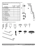
Parts List.................................................................................................................................................................................3
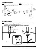
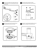
Installation to Mounting Surface .............................................................................................................................................4
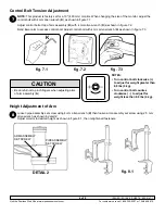
Control Bolt Tension Adjustment .............................................................................................................................................6
Arm Height Adjustment ...........................................................................................................................................................6
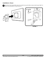
Installation to Screen ..............................................................................................................................................................7
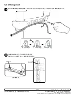
Cable Management ................................................................................................................................................................8

For customer care call (800) 865-2112 or (708) 865-8870.

WARNING

•  Do not begin to install your Peerless product until you have read and understood the instructions and warnings 

contained in this Installation Sheet. If you have any questions regarding any of the instructions or warnings, please 

call Peerless customer care at 1-800-865-2112.

•  This product should only be installed by someone of good mechanical aptitude, has experience with basic building 

construction, and fully understands these instructions.

•  Make sure that the supporting surface will safely support the combined load of the equipment and all attached 

hardware and components.

•  Never exceed the Maximum Load Capacity. See page one.
•  Always use an assistant or mechanical lifting equipment to safely lift and position equipment.
•  Tighten screws firmly, but do not overtighten. Overtightening can damage the items, greatly reducing their holding 

power.

•  Be sure to use designated fasteners and tools to assemble product. If correct fasteners and tools are not used, 

product may fail.

•  When using clamp mounted product do not install arm until clamp is securely attached to mounting surface.
•  When a monitor is not attached to arm assembly, arm may swing upward and cause harm to you or damage to 

product.

Summary of Contents for LCT-A1B6C

Page 1: ...0 800 729 0307 or 708 865 8870 Fax 708 865 2941 www peerlessmounts com ISSUED 02 18 09 SHEET 090 9167 1 Max Load Capacity 17 6 lb 8 kg Installation and Assembly Desktop Swivel Two Link Pole for 15 24 LCD monitors Models LCT A1B6C LCT A1B6H ...

Page 2: ...0 865 2112 This product should only be installed by someone of good mechanical aptitude has experience with basic building construction and fully understands these instructions Make sure that the supporting surface will safely support the combined load of the equipment and all attached hardware and components Never exceed the Maximum Load Capacity See page one Always use an assistant or mechanical...

Page 3: ...s shown are included with your product A B Description LCT A1B6C Part LCT A1B6H Part A pipe assembly 1 1 B arm assembly 1 1 C M4 x 10 mm screws 4 4 D M4 x 16 mm screws 4 4 e bar bushing 1 1 F cable guide 2 2 G lower pipe cap 1 1 H upper pipe cap 1 1 J M4 x 8 mm screws 4 4 K 4 mm allen wrench 1 1 L 2 5 mm allen wrench 1 1 M bolt 1 N spring washer 1 o flat washer 1 P bottom washer 1 Q 8 mm wrench 1 ...

Page 4: ...e Place pipe assembly A onto mounting surface and secure using one bolt M one spring washer N one flat washer O and one bottom washer P as shown in figure 2 1 Tighten bolt M using 8 mm wrench Q as shown in figure 2 2 NOTE Be sure fasteners and washers are assembled in correct order as shown in detail 1 Turn handle to tighten pipe assembly A to mounting surface until firmly attached DETAIL 1 1 3 3 ...

Page 5: ...bar bushing E through pipe and align with set screw then place arm assembly B onto pipe assembly A Attach lower pipe cap G to top of pipe assembly A using two M4 x 8 mm screws J 33 3 4 Attach upper pipe cap H to lower pipe cap as shown below until click sound is heard Adjust arm to desired height and tighten set screw on both arms using 2 5 mm allen wrench L 5 6 H G ...

Page 6: ...lt with 4 mm allen wrench K as shown in figure 7 3 7 Control Bolt Tension Adjustment fig 7 1 fig 7 2 fig 7 3 K Loosen pipe assembly set screw using 4 mm allen wrench K then loosen arm assembly set screw using 2 5 mm allen wrench as shown in detail 2 Adjust monitor to desired height as shown in figure 8 1 then retighten all fasteners 8 Height Adjustment of Arm DETAIL 2 fig 8 1 ARM ASSEMBLY SET SCRE...

Page 7: ...ounts com For customer care call 1 800 729 0307 or 708 865 8870 7 of 8 9 Installation to Screen Attach front of arm assembly B to back of screen with four screws C or D as shown in detail 3 using VESA 75 or VESA 100 mounting pattern as shown in figure 9 1 C or D DETAIL 3 fig 9 1 ...

Page 8: ...h cable guide F and attach to arm using one M4 x 8 mm screw J as shown below 10 Cable Management 2009 Peerless Industries Inc All rights reserved All other brand and product names are trademarks or registered trademarks of their respective owners J F Cords may also route through arm assembly Open gap to press fit cables as shown in detail 4 11 cable cable DETAIL 4 ...

Reviews: