
ISSUED: 02-18-09 SHEET #: 090-9167-1
Visit the Peerless Web Site at www.peerlessmounts.com
For customer care call 1-800-729-0307 or 708-865-8870.
6 of 8
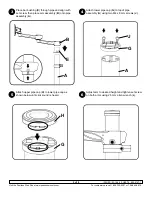
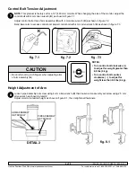
NoTe:
This product is factory set for a 19" (483 mm) monitor. When changing the size of the monitor, adjust the
control bolt with 4 mm allen wrench (
K
) as shown in figure 7.1.
Adjust control bolt at top of arm assembly (
B
) with 4 mm allen wrench (
K
) as shown in figure 7.2.
Bend lower arm to access control bolt. Adjust control bolt with 4 mm allen wrench (
K
) as shown in figure 7.3.
7
Control Bolt Tension Adjustment
fig. 7.1
fig. 7.2
fig. 7.3
K
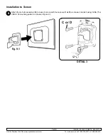
Loosen pipe assembly set screw using 4 mm allen wrench (
K
) then loosen arm assembly set screw using 2.5 mm
allen wrench as shown in detail 2.
Adjust monitor to desired height as shown in figure 8.1, then retighten all fasteners.
8
Height Adjustment of Arm
DeTAIL 2
fig. 8.1
ARM ASSEMBLY
SET SCREW
PIPE ASSEMBLY
SET SCREW
NoTeS:
• Turn control bolt clockwise (+)
to adjust for weight greater than
8.8 lbs (4 kg).
• Turn control bolt counter-
clockwise ( - ) to adjust for
weight less than 8.8 lbs (4 kg).
• Be careful not to pinch fingers when adjusting arms
of arm assembly (
A
).
CAUTIoN


