background image

2 of 6

ISSUED: 07-23-03   SHEET #: 201-9073-4  07-14-05

Visit the Peerless Web Site at www.peerlessmounts.com

For customer care call 1-800-729-0307 or 708-865-8870.

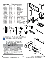
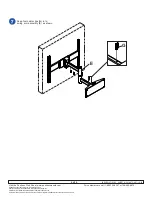
Use wall bracket as a template to mark and drill four
5/32" (4 mm) dia. holes to a minimum depth of 2.5"
(64 mm). Make sure wall plate (

A

) is level and attach

using #14 x 2 1/2" (6 mm x 38 mm) wood screws (

J

)

and screw head covers (

K

). Tighten screws with

phillips screwdriver (not provided) and push screw
head cover over wood screw heads.

A

Installation To Wood Stud Walls

Q

L

Before you start make sure all parts
listed are included with your product.

PART #

PART #

QTY.

DESCRIPTION

PLA 2

PLA 2S

A

200-1413

200-4413

1

wall bracket

B

200-1418

200-4418

1

swivel weldment

C

200-1052

200-1052

1

wall support arm axle

D

200-1483

200-4483

1

swivel bracket

E

200-0437

200-0441

1

swing arm assembly

F

200-0439

200-0440

1

roll pitch assembly

G

590-1089

590-1089

4

cable clip

H

5M9-025-X02

5M9-025-X02

1

holding pin

I

560-9641

560-9641

1

snap ring

J

5S1-015-C03

5S1-015-C04

4

#14 x 2.5" hex head phillips screw

K

560-1029

560-2029

4

3/8" screw head cover

L

520-1068

520-2068

4

M8 x 15 mm socket pin screw

M

520-1066

520-2066

4

M6 x 10 mm socket pin screw

N

590-0097

590-0097

4

alligator anchor

O

520-9263

520-2176

4

M10 x 1.5" x 15 mm penta-pin screw

P

520-9260

520-9260

1

M10 x 2" penta-pin driver

Q

560-9646

560-9646

1

4 mm security allen wrench

Parts List

Some parts may appear slightly different than illustrated.

A

M

K

B

C

G

E

I

D

F

H

J

O

P

K

J

N

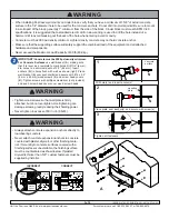
• Tighten wood screws so that wall bracket is firmly

attached, but do not overtighten. Overtightening can
damage screws, greatly reducing their holding power.

• Never tighten in excess of 80 in • lb (9 N.M.).

• Make sure that mounting screws are anchored into the

center of the studs. The use of an "edge to edge" stud
finder is highly recommended.

WARNING

Summary of Contents for Solid-Point PLA 2

Page 1: ...allations To Wood Stud Walls page 2 To Solid Concrete Concrete Block or Brick Walls page 3 Two instruction sheets are included with your product Begin with this sheet It is the responsibility of the installer to verify that the supporting surface will safely support the combined load of all attached hardware and components Use an assistant or mechanical lifting equipment to safely lift and positio...

Page 2: ... 1 swing arm assembly F 200 0439 200 0440 1 roll pitch assembly G 590 1089 590 1089 4 cable clip H 5M9 025 X02 5M9 025 X02 1 holding pin I 560 9641 560 9641 1 snap ring J 5S1 015 C03 5S1 015 C04 4 14 x 2 5 hex head phillips screw K 560 1029 560 2029 4 3 8 screw head cover L 520 1068 520 2068 4 M8 x 15 mm socket pin screw M 520 1066 520 2066 4 M6 x 10 mm socket pin screw N 590 0097 590 0097 4 allig...

Page 3: ...TM C 90 specifications It is suggested that a standard electric drill on slow setting is used to drill the hole instead of a hammer drill to avoid breaking out the back of the hole when entering a void or cavity Concrete must be 2000 psi density minimum Lighter density concrete may not hold concrete anchor Make sure that the supporting surface will safely support the combined load of the equipment...

Page 4: ...C protruding from wall bracket A as shown SNAP RING INSTALLATION Pull snap ring apart Wind it around the tube while feeding it into the groove Finish by snapping the end of the snap ring into groove NOTE Fit of axle C into wall bracket A and lower swing arm E will be tight Gently tap into place with a hammer if necessary I H E groove 1 3 2 groove I C A Insert swivel weldment B through swing arm E ...

Page 5: ...screws O BACK OF PLASMA ADAPTER PLATE ADAPTER PLATE AND SCREEN MAY APPEAR DIFFERENT THAN ILLUSTRATED Insert two M8 screws L into roll pitch assembly F Leave approx 1 4 of exposed thread as shown in detail Hook roll pitch assembly monitor onto swivel bracket D L L D Adjust tilt as needed and secure with two M8 x 15 mm screws L Use allen wrench Q to tighten screws 1 4 CUTAWAY VIEW Use an assistant o...

Page 6: ...65 8870 2005 Peerless Industries Inc All rights reserved Peerless is a registered trademark of Peerless Industries Inc Solid Point is a trademark of trademark of Peerless Industries Inc All other brand and product names are trademarks or registered trademarks of their respective owners Snap four cable clips G in to swing arm assembly E as shown G E ...

Reviews: