


ISSUED: 05-25-05 SHEET #: 055-9247-6 11-08-06
Visit the Peerless Web Site at www.peerlessmounts.com
3 of 7
For customer care call 1-800-729-0307 or 708-865-8870.
F
F
G
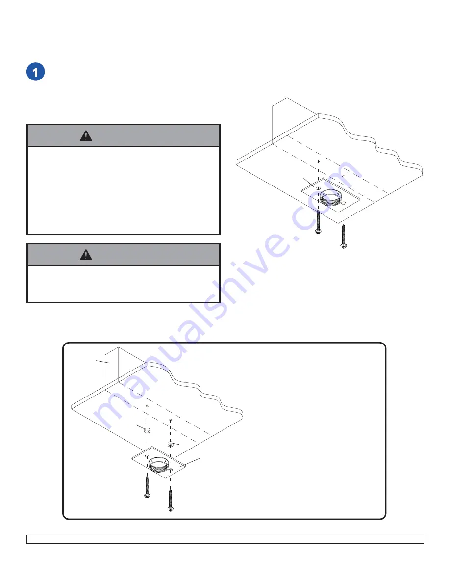
WOOD
JOIST
CEILING
Drill two 5/32" (4 mm) dia. holes to a minimum
depth of 2.5" (64 mm). Attach ceiling plate (
G
)
with two #14 x 2.5" (6 mm x 65 mm) wood
screws (
F
) as shown using 3/8" (10 mm) socket
wrench.
Skip to step 2.
IMPORTANT: Be sure to drill holes into the
joist CENTER!
For optional Cord Management,
install two spacers (
H
) between ceiling
plate (
G
) and ceiling.
Installation To Wood Joist Finished Ceilings,
Exposed Wood Joists, or Wood Beam Ceilings
WOOD
JOIST
CEILING
F
F
G
H
H
• Tighten wood screws (
F
) so that wall plate (
G
) is firmly
attached, but do not overtighten. Overtightening can
damage the screws, greatly reducing their holding
power.
• Never tighten in excess of 80 in • lb (9 N.M.).
• Make sure that mounting screws are anchored into the
center of the studs. The use of an "edge to edge" stud
finder is highly recommended.
WARNING
• It is the responsibility of the installer to verify that the
supporting surface will safely support the combined
load of all attached hardware and components.
WARNING


