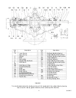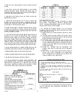
f. Remove glands (17), and mechanical seal stationary
elements (65). Remove mechanical seal rotating
elements (80).
g. Unless shaft sleeves (14 & 14A) are being replaced,
there is no need to remove the shaft collars (80A).
h. Loosen shaft sleeve set screws then loosen shaft
sleeves (14 & 14A) with a spanner wrench. Sleeve (14)
has right-hand thread, sleeve (14A) has left-hand thread.
Remove sleeves from shaft.
NOTE
A seal between the shaft and sleeve is made with an O-
ring (14B) in a groove in the sleeve. Use care not to
damage the O-ring.
NOTE
The interference between impeller hub ID and shaft OD
meets ANSI B4.1 standards for “Preferred Limits and
Fits for Cylindrical Parts” and corresponds to standard fit
LC-1.
i. Remove impeller (2) and impeller key (32) from
shaft (6).
1-4. CLEANING. Clean all metal parts (except bearings)
with a solvent. Use a bristle brush (NOT metal or wire) to
remove tightly adhering deposits. A fiber scraper may be
used to remove the gasket and shellac from casing
flanges.
2-1. INSPECTION. Visually inspect parts for damage
affecting serviceability or sealing. Emphasize inspection
of mating parts having relative motion – wear rings and
mechanical seal faces. Perform detail inspection as
follows:
a. Check all O-rings and bearing cover gaskets for
cracks, nicks or tears. Replace if defective in any way.
b. Mount the shaft between centers or on vee blocks.
Check for eccentricity throughout entire length with a dial
indicator; eccentricity must not exceed 0.003 inch total
indicator reading. Check that threads are clean and
sharp. Surfaces on which bearings mount must be
smooth, have a finish of 32 micro inches or better, and
the shoulders square and free from nicks.
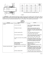
c. Measure the OD of the impeller wear surface or
impeller ring (8) and the ID of the casing ring (7).
Compute the diametrical clearance (ID minus OD) and
compare with the limits given in Table I. If measured
diametrical clearance exceeds two times values in Table
I, repair to restore design clearance is recommended. ID
surface of casing ring must be smooth and concentric
with ring OD.
d. Examine impeller passages for cracks, dents, gouges
or embedded material.
e. Examine the mechanical seal for wear at the seal
faces and for damage to the bellows. Replace the com-
4851959
a. Blow dry with clean dry compressed air.
Peerless Pump does not recommend reuse of ball
bearings after removal from the shaft. If you choose to
clean and consider reuse, proceed as follows.
b. To clean ball bearings, remove bearings from housings.
c. Place bearings in wire basket so there is space for
cleaner to reach all parts.
d. Immerse in Stoddard solvent. Agitate basket until
grease is thoroughly loosened and can be flushed out.
e. Place bearings on a screened surface.
f. Using a spray gun with air filter and clean Stoddard
solvent, flush each bearing until all grease and sludge is
removed.
g. Blow solvent out of bearings with dry filtered air.
h. Lubricate bearings immediately after cleaning with light
spindle oil and place them in a covered container.
i. Do not spin bearings during cleaning.
1-5. REMOVAL OR REPLACEMENT. Refer to the
Disassembly Instructions for disassembly to the point of
removing bearings from the shaft. Normally, they should
be removed only to clean and inspect after operating
trouble is traced to the bearings.
SECTION II – INSPECTION AND REPAIR
plete seal if scoring or hardening of the bellows is
evident, or if the lapped seal faces are cracked, nicked
or scored.
2-2. REPAIR. Make needed repairs in the following
manner:
a. If ID of casing rings (7) is grooved, scored or
eccentric, replace the casing rings.
b. If impeller wear surfaces or impeller rings (8) are
defective, the impeller must be machined to install new
impeller rings. Be sure machining is concentric with
impeller bore. Use care NOT to reduce hub OD when
machining off old impeller rings.
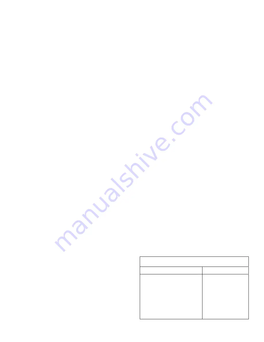
TABLE I
IMPELLER/CASE WEAR RING
DIAMETRICAL CLEARANCE
.015/.019 .018/.022
2AE11 3AE9 3AE14
4AE10 4AE11 4AE12
5AE8 5AE11 5AE12
5AE14 6AE10
6AE11 6AE12 6AE14
6AE16 6AE18 8AE12
8AE13 8AE15 8AE17
8AE20 10AE12
10AE14 10AE20
10AE16
4

