NOTE
Clearances in Table I are for standard bronze or cast iron
fitted pumps. For materials with a tendency to gall, such as
stainless steel, increase clearances by .010 inch.
NOTE
For bronze impellers and rings, the rings are shrunk on the
hub according to standard fit FN-4 of ANSI B4.1.
Hardened impeller rings are installed according to ANSI
B4.1 standard fit FN-1.
c. Install new impeller rings (8) on the impeller (shrink or
press depending on material). The impeller ring ID is
factory-machined for proper fit.
NOTE
Standard pumps are furnished without impeller rings; the
wear surface is an integral part of the impeller. Impeller
wear rings maybe field-installed by machining. Refer to
note following paragraph 2-2b for standard fits to be
produced when making such repair. Replace impellers
which cannot be salvaged by such repair.
d. Replace worn shaft sleeves.
e. Straighten or replace shafts having excessive run-out
(eccentricity). See paragraph 2-1b.
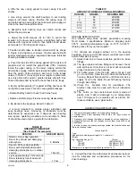
3-1. ROTATING ELEMENT. (See Figure 1) Reassemble
as follows:
a. Coat the shaft (6) lightly with oil.
b. Place impeller key (32) in shaft keyway.
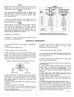
c. Align impeller (2) on shaft and install with an arbor
press or brass tubular sleeve and hammer. Guard against
bending shaft. When assembled, the impeller vanes must
rotate in the proper direction. (See Figure 3), and impeller
hub must be centered on shaft journal.
FIGURE 3. VANE POSITION FOR PROPER ROTATION
d. Coat shaft sleeve O-rings (14B) with oil and install in
shaft sleeves (14 & 14A). Install shaft sleeve set screws in
shaft sleeves. Assemble shaft sleeves to the shaft and
hand tighten against the impeller. Do not tighten shaft
sleeve set screws.
e. Install the shaft collars (80A). Do not tighten set screws
at this time.
f. Locate casing rings (7) on impeller.
g. Lightly lubricate the O.D. of the shaft sleeves (14 &
14A), and install the mechanical seal rotating elements
(80) over the shaft sleeves.
h. Lightly lubricated the O-rings on the O.D. of the
TABLE II
TORQUE VALUE (FT.-LB.)*
SIZE
INCH
MEDIUM CARBON
STEEL
SAE J429 GRADE 5
105-120,000 PSI
TENSILE
MEDIUM CARBON
ALLOY STEEL
SAE J429 GRADE 8
150,000 PSI
TENSILE
1/4 7-8
8-9
3/8 23-25
32-34
1/2 59-62
76-83
5/8 120-125
151-166
3/4 210-225
268-295
7/8 305-325
433-477
1 421-465
648-715
HEAD
SYMBOLS
*TORQUE VALUES SHOWN ARE FOR CLEAN
LUBRICATED THREADS, AND GASKETED JOINTS.
SECTION III - REASSEMBLY
mechanical seal stationary elements (65), and install
stationary elements into glands (17). Place these
assemblies over the shaft sleeves.
i. Place inboard deflectors (40A) on shaft.
j. If previously removed, install bearing housing seals
(169) into housings (31 & 33). Insert bearings (16 & 18),
into housings (31 & 33).
k. Press housing-bearing-seal assemblies on shaft to seat
bearings against shaft shoulders.
l. Install bearing retaining ring (18A) in groove against the
outboard bearing.
m. Install gaskets (73B) on bearing covers. Use factory
supplied parts or cut replacement gaskets from 1/16 inch
No. 444 Vellumoid (SAE P3415A).
EXCEPTION
: For all
models using 3306 size outboard bearing, gasket 73B is
1/32 thick.
n. Attach inboard and outboard bearing covers (35, 37). In
the assembled position, the grease drain tap must be
located at bottom in a horizontal plane.
o. Install outboard deflector (40B), and coupling key (46);
assemble coupling half on the shaft and tighten the
setscrews.
3-2. PUMP. Complete the assembly of pump as follows:
a. Use factory supplied casing gasket (73A) or use the
upper casing (1B) as a template to cut a casing gasket
(73A) from 1/64 inch Vellumoid (SAE P3313B). It is very
important that specified material and thickness be used for
casing gasket. Machined surfaces of both casings must be
perfectly clean and free from burrs and nicks.
5
5
4851959

