b. Affix the new casing gasket to lower casing (1A) with
shellac.
c. Use slings around the shaft bearings to set rotating
element into lower casing. Position the casing rings (7)
and both bearing housings so that all dowel pins engage in
slots in the lower case split surface.
d. Assemble both bearing caps per match marks and
tighten the cap screws.
e. Adjust the shaft sleeves (14 & 14A) to center the
impeller in the lower casing volute, and tighten both shaft
sleeves with a spanner wrench, then tighten shaft sleeve
set screws to 130 inch-pounds torque.
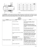
f. Position shaft collars to location dimension D as shown
in Figure 2 and tighten set screws. If pump was built with
special mechanical seals, a separate sheet was furnished
showing installation details.
g. Cover the top side of the casing gasket with a mixture of
graphite and oil. Install the gland bolts (17B). Carefully
locate the upper casing on the lower, making certain the
dowel pins engage. Install cap screws and tighten, working
from the center of the casing to each end, to the torque
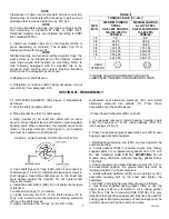
values in Table II. If any cap screws require replacement,
use only parts with equal or greater tensile strength. See
Table Ii. Rotate shaft by hand to check that it turns freely.
h. Evenly tighten glands (17) against stuffing box faces. Do
not tighten excessively. This can cause gland breakage.
i. Rotate shaft by hand to check that it turns freely.
j. Replace all drain plugs if removed during disassembly.
k. Re-lubricate the bearings. Refer to Table IV.
It is most important to provide proper lubrication and
keep bearings clean. Frequency of lubrication must be
determined by experience, as it depends upon bearing
size, speed, operating conditions and environment. Table
III should be used only as a guide for re-lubrication.
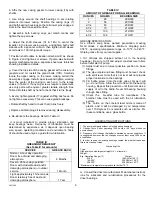
TABLE III
GREASING FREQUENCY
(See Table IV for amounts)
SERVICE GREASE
EACH
Normal, 8-hour day operation.
Room free of dust and damaging
atmosphere.
6 Months
Severe, 24-hour day operation.
Room with moderate dust and/or
damaging atmosphere, or outdoor
service.
1 Month
Light, approximately 10-hour week.
Room relatively free of dust and
damaging atmosphere.
1 Year
4851959
TABLE IV
AMOUNT OF GREASE FOR BALL BEARINGS
OUNCES GRAMS
BEARING
SIZE
1 28
206/305
2 56
207/306
2-1/4 63
208/307
2-1/2 70
210/308
3-1/2 100
212/310
4-1/2 128
213/311
GREASE SPECIFICATION:
Use Lithium soap base, worked penetration, meeting
NLGI Grade 2 specifications. Minimum dropping point
355 ºF., operating temperature range of –10 ºF. to 240 ºF.
Obtain grease from you local supplier.
l. Oil. (Pumps are shipped without oil in the bearing
housings.) Be sure to fill and adjust constant level oilers
before initial start of pump.
(1) Adjust dust cap to lowest possible position on base
fittings.
(2) The pipe nipple and base fitting must be level; check
with spirit level. Oiler that is not level will not provide
proper lubrication to the bearings.
(3) Fill bottle, screw it into the dust cap as far as it will
go –do not force. Allow the oil to flow into the bearing
housing. Repeat this procedure until there remains a
supply of oil in the bottle. Never fill bearing housing
through base fitting.
(4) Check the breather tube for cleanliness. The
breather tube must be used with the oil lubrication
system.
(5) The bottle on the constant level oilers is made of
plastic, and it will be damaged by oil temperature
over 170 degrees F or solvents such as alcohol. For
these conditions, use a glass bottle.
LUBRICATING INSTRUCTIONS
1. The pump is shipped without oil in the bearing housings.
2. Change first oil after operating 1000 hours or 60 days, whichever
occurs sooner.
3. Frequency of oil change thereafter is dictated by service conditions. It
is suggested, however, that oil changes occur at least every 3000 hours
of operation.
4. In order to keep the bearing housings vented, the breather tubes and
filters must be kept clean.
Lubricating Oils
Type:
High quality non-detergent straight H.V.I. mineral oil.
Weight:
Brg. Operating Range (ºF) Weight
0-150 150 SSU at 100 ºF.
150-200* 300 SSU at 100 ºF.
200-250* 500 SSU at 100 ºF.
*Maximum oil temperature in plastic oiler bottle 170 ºF.
m. Consult the driver manufacturer’s Maintenance instruct-
ions for lubricants and re-lubrication procedures for the
driver bearings
.
6

