background image

4.8 Starting up the product

4.8.1 Starting the pump

1.

Open the inlet valve completely, and close the outlet valve
completely.

2.

Switch the power supply on.

3.

Start the pump.

4.

Immediately make a visual check of the pump and inlet pipe.

5.

Allow the pump to ramp up to full speed.

6.

Slowly open the outlet valve until the operational flow is
achieved.

7.

Check the outlet pipe for leaks.

8.

Open the isolating valves for the pressure gauges.

9.

Record the pressure readings.

10. Verify that the pump performance is within the tolerance of the

pump performance curve.

4.8.1.1 Air in the system

Entrained air reduces pump total head and flow rate.

Use an eccentric reducer on the inlet pipe.
Return lines into tanks should terminate a minimum of two
pipe diameters below the low liquid level.

4.8.1.2 Checking the driver lubrication

Before running the drivers either separately or connected to the
pump:
1.

Follow the driver manufacturer instructions for lubrication
requirements.

2.

Ensure that the grease-lubricated bearings in the driver have
been properly greased with the grade of grease recommended
by the driver manufacturer. 

4.8.1.3 Driver settings

Refer to the manufacturer's instructions.

4.8.1.4 Pump performance

Initial field test data becomes a valuable baseline for
future troubleshooting and maintenance. It may not be
possible to match the factory performance due to
differences in system resistance. 

Once the pump is operating, verify the following:
1.

The pipe connections are tight, and no leaks are present.

2.

The following attributes match the pump nameplate:
a. operating speed
b. flow rate
c. inlet and outlet pressure
d. power input, P1.

5. Storing and handling the product

5.1 Short-term storage

Standard factory packaging is suitable for protection during
shipment and during covered storage at a job site for a short period
between installation and startup. The preservatives applied at the
factory have an effective life of two to three months from the date of
shipment from the factory, depending on the severity of the
environment in which the equipment is exposed. For international
destinations, this will vary depending on the seaworthiness of
export boxing.

5.1.1 Controlled storage

Storage facilities should be maintained at an even temperature with
a relative humidity lower than 50%, and little or no dust.  Inspect
and recoat the equipment periodically with water displacement rust
inhibitor, vapor phase inhibitor, or rust preventive coating.The
equipment must be inspected weekly to ensure that all
preservatives are intact, and internals are protected. 

5.1.2 Uncontrolled storage

For uncontrolled storage periods of three months or less, inspect
the equipment weekly to ensure preservatives are intact and
internal parts are protected.

Preparing the product for uncontrolled storage


Periodically inspect and recoat the equipment with rust and
vapor phase corrosion inhibitors.

Seal all pipe threads and flanged pipe covers with tape. Place
an adequate amount of desiccant near the center of the pump.

If the pump is assembled, place and securely fasten
additional desiccant in the outlet of the pump. 

Cover the equipment with black polyethylene or equivalent,
with a minimum thickness of 0.006 in (0.15 mm).

Provide a ventilation hole approximately the size of a small
coin. 

Provide protection from direct exposure to the environment.

If applicable, connect space heaters on equipment such
as motors, engines or controls.

5.1.3 Short-term storage

The pump and equipment, as shipped, have adequate
protection for short-term storage for up to three months. 

If the product is not to be installed and operated immediately
after receiving it, store it in a clean, dry area at a moderate
ambient temperature.

For packed-type pumps, the packing glands may be left on the
pump shaft and securely fastened in position. All exposed
machined surfaces should be thoroughly coated with a film of
rust preventative material.

For packed-type pumps, the stuffing box packing must be
removed and stored in a sealed plastic bag. Seal the end of the
stuffing box with rolled vapor phase inhibitor paper and seal
with weatherproof tape.

Rotate the shaft by hand periodically, at least monthly, to coat
the bearing with a lubricant to retard oxidation and corrosion.

Make sure the pump cannot roll or fall over.

Follow the motor manufacturer's storage recommendations
where applicable.

5.1.4 Long-term storage

Long-term storage protection provided by the factory does not
extend the warranty in any manner.

The warranty is valid only if the equipment is properly handled
and stored.

In case of storage up to six months or longer, the pump must
be protected against heat and moisture as described in the
previous sections.

Periodically, at least monthly, manually rotate the shaft to coat
the bearing with a lubricant to retard oxidation and corrosion.

Ensure that the pump cannot roll or fall over.

Follow the motor manufacturer's storage recommendations
where applicable.

Inspect the pump before putting it into operation. Make sure
that the impeller can rotate freely. Pay special attention to the
condition of the shaft seals or the packing and O-rings.

5.1.5 Accessories storage

Store accessories according to the manufacturer's instructions.

14

English (US)

Summary of Contents for AEF

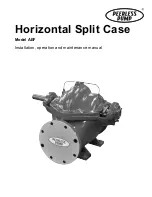
Page 1: ...Horizontal Split Case Model AEF Installation operation and maintenance manual ...

Page 2: ......

Page 3: ...Horizontal Split Case English US Installation and operating instructions 4 3 Table of contents ...

Page 4: ... caused by abrasive materials nor does it cover damage resulting from misuse accident neglect or from improper operation maintenance installation modification or adjustment This warranty does not cover parts repaired outside seller s factory without prior written approval Seller makes no warranty as to starting equipment electrical apparatus or other material not of its manufacture If purchaser or...

Page 5: ...tagged Pumping equipment especially fire pumps can start up at any time It is imperative to isolate the engine before doing any maintenance work Switch off the main power supply remove fuses secure fuel lines apply lock outs where applicable and affix suitable isolation warning signs to prevent inadvertent re connection Isolate the fuel supply to the engine before working on any part of the fuel s...

Page 6: ... Excessive noise Death or serious personal injury If the operating noise level of the product exceeds local code or safe levels over 85 dBA the product must be installed in a controlled access area Provide ear protection to persons authorized to be in this area Fire pumps can start unexpectedly at any time Ear protection should be carried by or readily available to all persons authorized to be in ...

Page 7: ... s response to accelerations and the foundation supporting the pump If a seismic analysis is required please refer to the governing bodies recommended for grouting and foundation requirements The customer must supply complete specifications for earthquake resistance requirements including seismic criteria acceleration magnitudes frequency spectrum location and direction relative to the pump and qu...

Page 8: ...shed put nuts on the anchor bolts and tighten them just enough to keep the base plate from moving 6 Construct a formwork around the concrete foundation and pour grout inside the base plate The grout will compensate for the uneven foundation distribute the weight of the pump and prevent shifting Use an approved non shrinking grout 7 Allow for the grout to cure fully before proceeding with torquing ...

Page 9: ... the tapped holes on the pump inlet and outlet flanges or pipes Pressure gauges will enable the operator to monitor the pump performance and determine whether the pump conforms to the parameters of the performance curve If cavitation vapor binding or other unstable operating situations occur the pressure gauges will indicate with wide fluctuation in the inlet and outlet pressures 3 5 1 2 Vibration...

Page 10: ...tening the flange bolts To facilitate accurate field alignment we do not dowel the pumps or drivers on the base plates before shipment If the product does not stay in alignment after installation possible causes of misalignment are setting seasoning or springing of the foundation excessive force on the pipes distorting or shifting the machine settling of the building shifting of pump or driver on ...

Page 11: ...40 1650 0 011 0 28 0 013 0 33 392 177 8 253000 28585 3 5 3 3 Coupling gap and maximum misalignment KTR ROTEX size E distance Max parallel Max angularity Max axial in mm in mm in mm in mm 14 0 51 13 0 006 0 15 1 1 28 0 02 0 5 0 04 1 19 0 63 16 0 007 0 18 1 25 0 02 0 5 0 05 1 3 24 0 71 18 0 008 0 2 0 08 2 0 02 0 5 0 06 1 5 28 0 79 20 1 0 009 0 23 0 09 2 0 03 0 8 0 06 1 5 38 0 94 23 9 0 01 0 25 0 09 ...

Page 12: ...naway speed A sudden power and or discharge valve failure during pump operation against a static head will result in a flow reversal and the pump will operate as a hydraulic turbine in a direction opposite to that of a normal pump operation If the driver offers little resistance while running backward the rotational speed may approach the pump specific speed This condition is called runaway speed ...

Page 13: ...trapped inside the impeller passages 4 7 Stuffing box The stuffing box gland must be loose when the pump is first put into operation Tightly pressed packing will result in burnt packing and scoring of the shaft or shaft sleeve The stuffing box should slowly leak fluid 40 60 drops per minute during operation When the leak can no longer be controlled by adjusting the stuffing box gland add one addit...

Page 14: ...servatives are intact and internals are protected 5 1 2 Uncontrolled storage For uncontrolled storage periods of three months or less inspect the equipment weekly to ensure preservatives are intact and internal parts are protected Preparing the product for uncontrolled storage Periodically inspect and recoat the equipment with rust and vapor phase corrosion inhibitors Seal all pipe threads and fla...

Page 15: ...ification 6 3 1 Nameplate Each pump has a nameplate with the pump s serial number You will find an example of the pump nameplate in the figure below Reference the serial number when contacting Peerless with questions or a service request A nameplate can also be found on the driver if supplied When requesting information about the driver both the driver serial number and the pump serial number will...

Page 16: ...cial UF UL listed and FM approved Approvals UC UL Canada listed approved UL UL listed approved FM cFMus approved 1 Cast iron ASTM 48 CL 35A or 40A Casing material 2 Ductile iron ASTM A536 60 40 18 3 316SS 4 316LSS 5 CD4MCu A84 9 Nickel aluminum bronze ASTM B148 X Special 1 Cast iron ASTM 48 CL 35A or 40A Impeller material 3 316SS 4 316LSS 5 CD4MCu A84 7 Silicon brass or bronze ASTM B584 9 Nickel a...

Page 17: ...r non freezing conditions the pump may remain filled with liquid Make sure that the pump is fully primed before restarting 4 For long shutdown periods or to isolate the pump for maintenance close the inlet and outlet gate valves If no inlet gate valve is used and the pump has positive inlet pressure drain all liquid from the inlet line to stop the liquid flow into the pump inlet 5 If applicable un...

Page 18: ... months Severe Duty approx 24 hours day Monthly Fasteners Check for loose fasteners Annually 8 2 1 Lubricant and sealant properties For sealing low pressure flange joints and similar applications use a product similar to Loctite 515 Lubricants with the properties mentioned in the tables below must be selected for lubrication in standard applications Compon ents Maximu m RPM Ambient operating tempe...

Page 19: ...rain the pump and isolate the pipes 4 Clear a space adjacent to the pump for storing components 5 Remove the couplings Follow the coupling manufacturer s instructions 6 Remove the water seal piping 127 7 Remove the nuts from the gland bolts 17B and remove the packing glands 17 from the shaft 6 8 Remove all fasteners from the upper casing 1B 9 Remove the bearing end cover 123 from the outboard bear...

Page 20: ...tion and to be replaced when worn to maintain optimal pump performance and service As the rings wear the clearance between the impeller and the volute increases as does the amount of liquid leaking from the high pressure to the low pressure zone The rate of wear depends on the characteristics of the pumped liquid The pump will typically have a volute wear ring and can also have an impeller wear ri...

Page 21: ...ign impeller 2 on the shaft and install with an arbor press or brass tubular sleeve and hammer When assembled the impeller vanes must rotate in the proper direction 6 Impeller hub must be centered on shaft journal 7 Apply a thread locker on the shaft sleeve set screws and install them in the shaft sleeves Assemble shaft sleeves to the shaft and hand tighten against the impeller Tighten the set scr...

Page 22: ... line intersects the packing container bore adjacent to the lantern ring and is not blocked by the packing 34 Replace the water seal piping The pipe supplying sealing liquid should be fitted tightly so that no air enters If the pumped liquid is dirty or gritty clean sealing liquid should be piped to the stuffing box in order to prevent damage to the packing and shaft sleeves Clear sealing liquid i...

Page 23: ...g cover 7 Casing wear ring 40A Inboard deflector 8 Impeller wear ring optional 40B Outboard deflector 13 Packing ring 41 Cap bearing inboard 14 14A Shaft sleeve RH LH 43 Cap bearing outboard 14B Shaft sleeve O ring 46 Coupling key 16 Inboard ball bearing 47 Inboard bearing cover seal 17 Packing gland 63 Stuffing box bushing 17B Gland bolt 73A Volute gasket not shown 18 Outboard ball bearing 73B Be...

Page 24: ...ing wear ring 37 Outboard bearing housing cover 8 Impeller wear ring optional 40A Inboard deflector 13 Packing ring 40B Outboard deflector 14 14A Shaft sleeve RH LH 41 Cap bearing inboard 14B Shaft sleeve O ring 43 Cap bearing outboard 16 Inboard ball bearing 46 Coupling key 17 Packing gland 47 Inboard bearing cover seal 17B Gland bolt 63 Stuffing box bushing 18 Outboard ball bearing 73A Volute ga...

Page 25: ...ver 8 Impeller wear ring optional 40A Inboard deflector 13 Packing ring 40B Outboard deflector 14 14A Shaft sleeve RH LH 41 Cap bearing inboard 14B Shaft sleeve O ring 43 Cap bearing outboard 16 Inboard ball bearing 46 Coupling key 17 Packing gland 47 Inboard bearing cover seal 17B Gland bolt 63 Stuffing box bushing 18 Outboard ball bearing 73A Volute gasket not shown 18A Bearing lock washer 73B B...

Page 26: ...d air or gas from liquid The strainer is clogged Clean the strainer The noise level has increased Poor alignment of the pump The inlet and outlet pipe clamps are loose Reestablish proper alignment of the pump and the motor Support the inlet and outlet pipes Make sure the vibration dampers flexible pipes and conduit connectors are installed correctly The foundation is cracked Repair the foundation ...

Page 27: ...educe the flow on the outlet side or fit the pump with a more powerful motor The shaft is bent Replace the whole rotation element and possibly the pump The stuffing box is too tight Retighten the stuffing box if possible Alternatively repair or replace the stuffing box The impeller clearance is too small causing rubbing or worn wear surfaces Adjust the impeller clearance if possible or replace the...

Page 28: ...layed in this material including but not limited to Peerless Pump and the Peerless Pump logo are registered trademarks owned by Peerless Pump All rights reserved 2019 Peerless Pump all rights reserved It is the policy of Peerless Pump to continually seek ways to improve its products and reserve the right to alter documentation without prior notice ...

Reviews: