8.2.4 Tightening torques
Proper tightening of fasteners is very important. The torque values
depend on the size and grade of the fasteners used. The values in
the table below apply to non-lubricated parts.
Fastener size
Torque
[lb-ft (Nm)]
Torque
[lb-ft (Nm)]
Medium carbon steel
SAE J429 Grade 5
105-120,000 psi
Tensile
Medium carbon alloy
steel
SAE J429 Grade 8
150,000 psi
Tensile
1/4-20
8 (10.8)
9 (12.2)
3/8-16
25 (33.9)
34 (46.1)
1/2-13
62 (84)
83 (112.5)
5/8-11
125 (169.5)
166 (225.1)
3/4-10
225 (305)
295 (400)
7/8-9
325 (441)
477 (646.7)
1-8
465 (630.5)
715 (969.4)
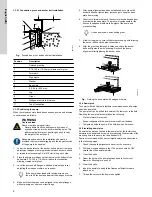
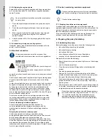
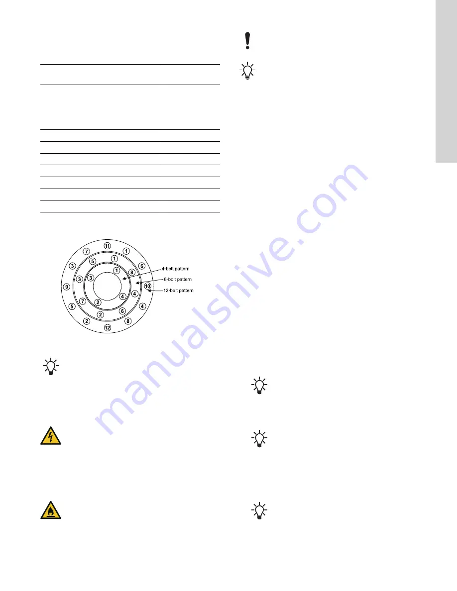
When assembling a pump, cross-tighten the screws in order to
avoid misalignment, binding and leakage.
TM073806
Fig.
Tightening pattern for 4-, 8-, or 12-bolt flange
Shaft sleeve set screws: 10.8 lb-ft (14.7 Nm)
The shown torque value is for clean lubricated threads and gasket
joints.
8.3 Dismantling the pump
WARNING
Electric shock
Death or serious personal injury
‐
Switch off the power supply before you start any work
on the product.
WARNING
Flammable material
Death or serious personal injury
‐
Contact Peerless for help related to removal of
impellers.
‐
Occasionally, the impeller has either been shrunk-fit
onto the pump shaft or has become difficult to remove
due to corrosion.
‐
If heat is applied to remove the impeller, it must be
applied cautiously. Before applying heat, ensure that
any residual hazardous liquid trapped between the
impeller and shaft has been drained and
thoroughly cleaned.
Peerless does not recommend reusing gaskets, O-rings,
packing rings, or ball bearings.
Before dismantling the pump, obtain a set of spare parts.
1.
Shut down the pump.
2.
Disconnect the power supply.
3.
Drain the pump and isolate the pipes.
4.
Clear a space adjacent to the pump for storing components.
5.
Remove the couplings. Follow the coupling manufacturer's
instructions.
6.
Remove the water seal piping (127).
7.
Remove the nuts from the gland bolts (17B), and remove the
packing glands (17) from the shaft (6).
8.
Remove all fasteners from the upper casing (1B).
9.
Remove the bearing end cover (123) from the outboard bearing
side.
10. Remove all fasteners from the bearing caps (41 & 43) located
on the lower casing (1A).
11. Create marks on the lower casing (1A) and bearing caps (41 &
43) for matching upon reassembly.
12. Screw the jack screws on the bottom of the lower casing (1A)
split flange to separate the upper and lower casing.
13. Unscrew the jack screws below the split flange surface to avoid
interference during reassembly.
14. For the 12AEF21, follow step a, for all other models follow step
b.
a. Optional removal: the bearing bracket, bearing, and bearing
housing can be removed for easier access to the packing
and lantern rings without having to remove the upper
casing.
b. Remove the upper casing by using a 1/2-13 UNC thread
eyebolt into the threaded hole.
15. Secure lifting straps around the shaft near the bearing
housings, and lift the rotating element from the volute.
Tap lightly on the underside of the bearing housings
to separate the housings from the brackets.
16. Place the rotating element on a convenient work surface.
17. Loosen the set screws, and remove the coupling.
Tap from the back of the hub or use a puller.
18. Remove coupling key (46) and outboard deflector (40B).
19. Take out the cap screws to remove the bearing covers (35 &
37) and the gaskets (73B).
20. Remove inboard bearing cover seal (47) from cover (35).
Required only if replacement of the seal is
necessary.
21. Remove the retaining ring (18A) from the outboard end of the
shaft.
19
English (US)

