TECHNICAL INSTRUCTIONS
4853989
10/ 2003
Our policy is one of continuous improvement and we reserve the right to alter specifications of our products at any time.
- 12 -
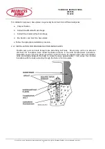
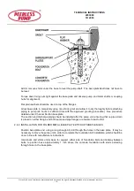
through the base plate lugs and fixtures inserted without disturbing the position of the pump unit.
Add or remove shims under the base to level the pump-shaft of horizontally mounted pump units. The
base plate itself does not have to be level.
Filling the frame with grout is not necessary, and is a purely optional detail, for aesthetic or cleanliness
reasons only. The delivery piping can be connected after pump unit installation, again ensuring no
strain is placed on the pump flanges.
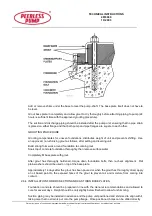
After completion, foundation bolts should be checked for tightness, then alignment checked.
2.7
ALIGNMENT PROCEDURE (Excluding Cardan Shafting)
The pump driver, if supplied, is correctly aligned on its base plate at the factory.
A certain amount of
deformation of the base plate is possible during transit and it is therefore essential to check alignment, prior
to final grouting and start up.
A flexible coupling will only compensate for a small amount of misalignment and should not be used to
compensate for excessive misalignment of the pump and driver shafts. Inaccurate alignment results in
vibration and excessive wear on the bearings, sleeve or shaft, and wear rings.
There are three forms of misalignment::
a.
Angular
b.
Parallel
c.
Axial
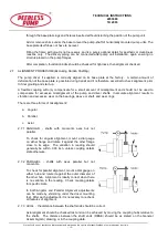
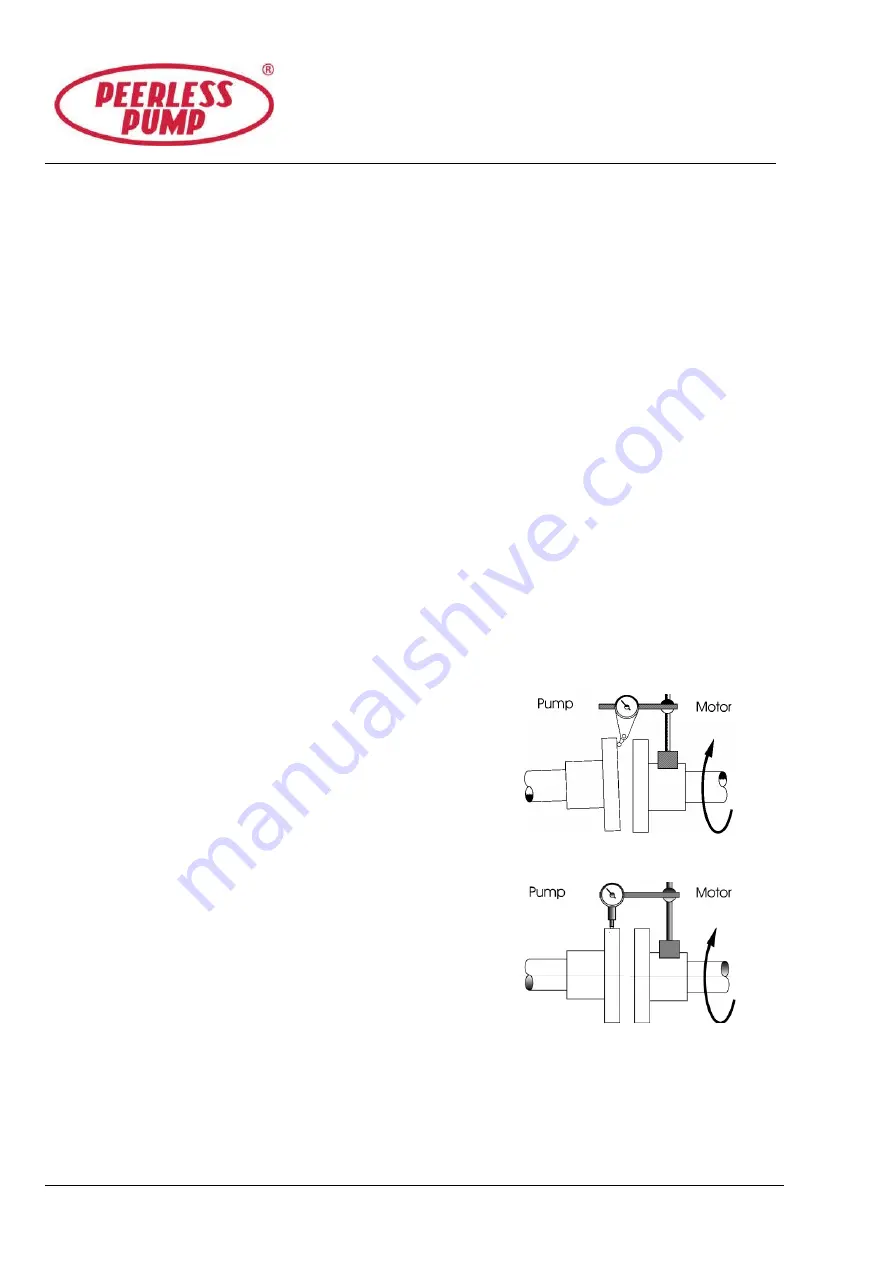
2.7.1 ANGULAR - shafts with concentric axes but not
parallel.
To check for angular alignment, mount a dial gauge
on either flange and rotate it against the other flange
close to its edge.
The variation in reading should
generally be within .003 inch, unless coupling details
state otherwise.
2.7.2 PARALLEL - shafts with axes parallel but not
concentric.
To check for parallel alignment, mount a dial gauge on
either hub and rotate it against the outer diameter of
the other hub. Alignment is ideally correct when there
is no variation in the reading. Check coupling details
for specific limits.
In both Angular and Parallel Alignment adjustments
can be made by shimming under the driver mounting
feet. After each adjustment, it is necessary to recheck
all features of alignment.
2.7.3 AXIAL - the distance between the shaft ends should be correct.
Axial alignment should be checked last and can be achieved by moving the coupling hubs relative to
the shafts.
The distance between the shaft ends (DBSE) should be as stated on the General
Assembly (GA) drawing, or in the coupling data.
Summary of Contents for HYF
Page 2: ......

