TECHNICAL INSTRUCTIONS
4853989
10/ 2003
Our policy is one of continuous improvement and we reserve the right to alter specifications of our products at any time.
- 17 -
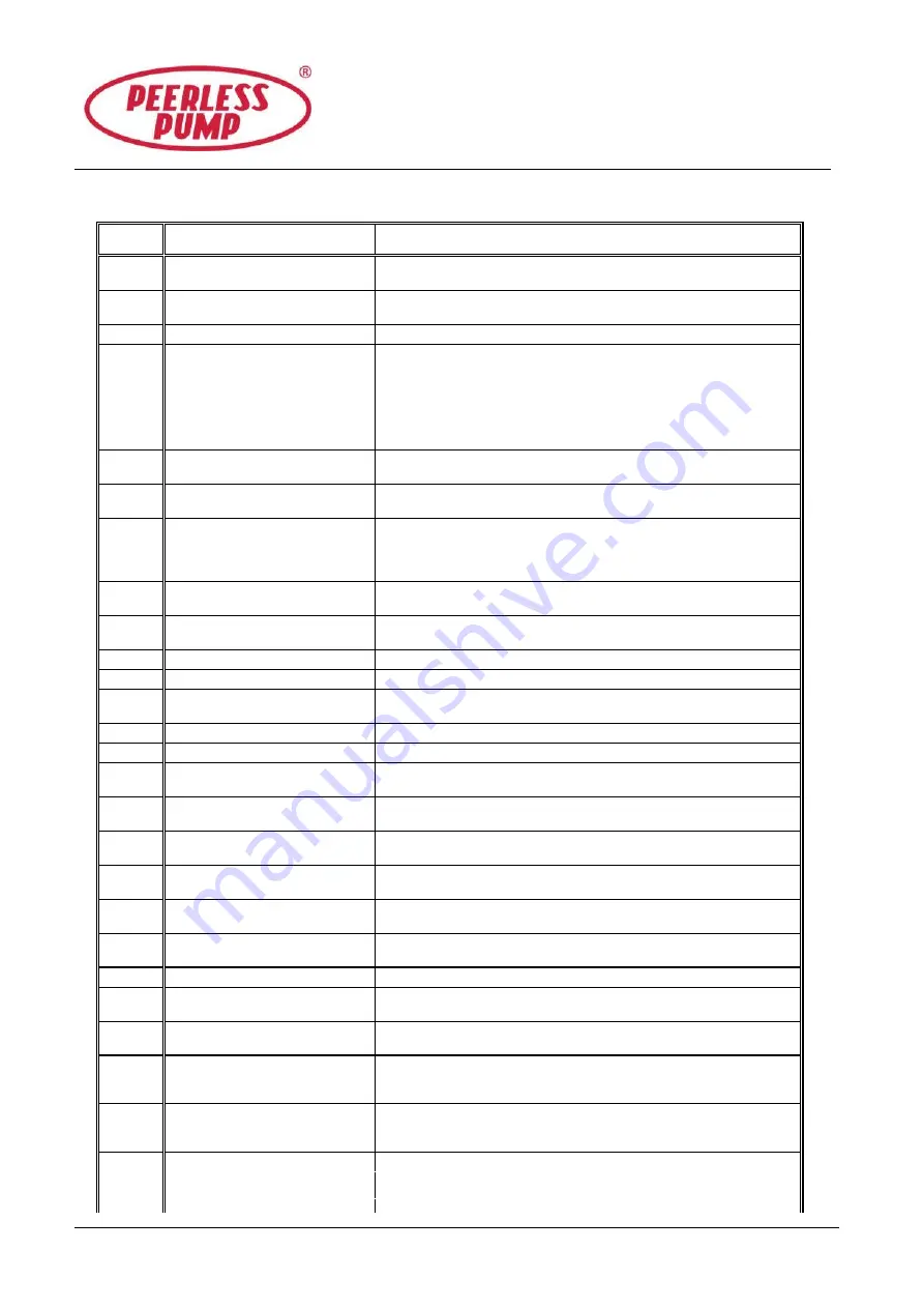
TABLE 2
FAULT RECTIFICATION CHART
FAULT
CAUSES
REMEDY
1
Pump not primed - lack of prime-
incomplete priming.
Fill pump and suction pipe completely with liquid.
2
Speed too low
Check whether motor is directly across-the-line and receiving full
voltage. Frequency may be too low. Motor may have an open phase.
3
Speed too high.
Check voltage on motor.
4
Air leak in suction.
Loss of prime.
If pumped liquid is water or non-explosive, find leak using flame around
flanges. For such liquid as gasoline, suction line can be tested by
shutting off or plugging inlet and putting line under pressure. Rectify leak
as appropriate.
Check for leaks in suction pipe joints and fittings; vent casing to remove
accumulated air.
5
Air or gas in liquid.
May be possible to over rate pump to the point where it will provide
adequate pressure despite condition.
6
Discharge head too high
Check pipe friction losses. Larger piping may correct condition. Check
that valves are fully open.
7
Suction lift too high.
If no obstruction at inlet, check for pipe friction losses.
Static lift may be too great, measure with vacuum gauge while pump
operates. If static lift is too high, liquid to be pumped must be raised or
pump lowered.
8
Not enough suction head for
liquid
Consult
PEERLESS PUMP COMPANY
.
9
Viscosity of liquid greater than
rating.
Use large driver. Consult supplier for recommended size.
10
Liquid heavier than rating.
Use larger driver. Consult supplier for recommended size.
11
Insufficient net inlet head.
Increase positive suction head on pump by lowering pump.
12
Impeller plugged up or partially
choked.
Dismantle pump and clean impeller.
13
Wrong direction of rotation.
Check motor rotation with directional arrow on pump casing.
14
Excessive wear ring clearance.
Dismantle, inspect and replace if necessary.
15
Damaged impeller.
Inspect impeller. Replace if damaged, or vane sections are badly
eroded.
16
Rotor binding.
Check deflection of rotor. Check bearings for damage or excessive
wear.
17
Defects in motor.
Check any motor defects. The motor may not be ventilated properly due
to a poor site location.
18
Voltage and/or frequency lower
than rating.
The voltage and frequency of the electrical current may be lower than
that for which the motor was rated. Consult supplier for correct supply.
19
Lubricating oil/grease dirty, or
contaminated.
Clean bearings and bearing housings as per instructions and re-
lubricate.
20
Foundation not rigid.
Check if foundation bolt nuts are drawn tight against base. Check the
foundations comply with the recommendations in instructions.
21
Misalignment of pump and driver.
Realign pump and driver.
22
Bearing worn.
Check bearings for damage and excessive wear. Any irregularities will
cause a drag on the shaft.
23
Rotor out of balance
Check for causes. Consult supplier.
24
Shaft bent.
Check deflection of rotor. Total indicator run-out should not exceed
0.002 inch (0.05mm) on shaft and 0.004 inch (0.1mm) on impeller wear
ring surface.
25
Impeller too small.
Check with supplier to see if a larger impeller can be used, otherwise cut
pipe losses or increase speed or both, but be careful not to overload
driver.
26
Air leak in stuffing box.
Increase seal lubricant pressure to above atmosphere.
Summary of Contents for HYF
Page 2: ......

