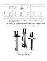
INTRODUCTION
UPON RECEIPT OF PUMP EQUIPMENT:
Check
carefully to see that all of the equipment has been
received. Report immediately any shortages or
damages to the transportation company handling the
shipment, noting the extent of the damage or
shortage on the freight bill and bill of lading.
Do not leave the unit exposed to weather or
construction hazards. The pump may become
mechanically damaged. This pump is a well designed
LOCATION:
The pump basin should be so located
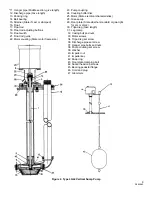
that the motor and pedestal (8, figure 2) are above
the floor level and are situated in a clean, drained,
well ventilated place, readily accessible for installa-
tion, inspection, and care of equipment. Overhead
room must allow for removal of the unit from the
basin for cleaning or repairs.
BASIN:
The basin should be constructed as tightly
as possible of a material such as steel plate, cast
iron, sewer tile, sewer crock, or concrete, depending
upon local requirements and personal preference.
Never discharge hot water or boiler blow-off into the
pump basin without first chilling. There must be at
least a 4-inch clearance below the strainer, the total
basin depth depending upon drainage requirements.
Pump parts, and the tools and
4. Replace the float rod and buttons to their original
positions.
lifting equipment used in install-
ation are heavy and may easily cause personal
injury if dropped or carelessly handled. The
normal precautions and safety rules associated with
the installation or repair of machinery, in regard to
manual lifting, use of power equipment, and
handling of tools, must be observed in the
installation of this pump.
FLOOR PLATE:
The split floor plate on the LG units
is adjustable and clamps firmly onto the hanger pipe
and discharge pipe at any level desired. The LGL2
bolts firmly to the motor pedestal and should be
firmly fixed over the basin using expansion bolts in
concrete or cap screws into an angle iron curbing or
basin cover. Three bolt-holes are provided in the floor
plate to insure a firm setting. Where a gas-tight unit
is provided, use a gasket ring under the floor plate
and vent the basin to the atmosphere, using the vent
opening provided in the floor plate.
Mounting the Floor Plate:
The floor plate is fixed in
location on LGA and LGL2 models. On the LGB units
the floor plate is furnished in two pieces marked
“left” and “right” which are held together by a bolt and
nut.
and carefully manufactured unit. It should be given
the same attention accorded to any precision
machine.
The satisfactory operation of a pump depends to a
large extent upon proper installation. These instruc-
tions cannot answer every question that may arise as
each installation will be different. The installer and
the operator of this equipment must use good
judgment to adapt these procedures to the
installation.
INSTALLATION
1. Before mounting the plate on the unit, loosen the
float rod buttons (18, figure 2) and remove the
float-rod assembly (16 and 17) from the unit by
lowering it out of the switch arm and float rod guide
(21).
2. Clamp the floor plate loosely to the hanger pipe
(10) and discharge pipe (12) at about the center of the
top hanger pipe, using the bolt and nut provided.
Make sure the half marked “right” is placed on the
float side of the unit.
3. Slip the plate up into place (check length desired),
line up the halves, and draw the nut up tight
clamping the plate firmly to the hanger pipe and
discharge pipe.
WARNING
FLOAT SWITCH ADJUSTMENT:
The unit may be
adjusted by raising or lowering the float rod
adjusting buttons (18) to start and stop the pump at
the desired levels of water in the basin. The
adjusting buttons should usually be set so that the
float drops to several inches above the pump casing
(6) and in rising closes the float switch 10 to 18
inches above this level; naturally this is varied
according to conditions.
MOUNTING TRIPOD LEGS:
On LGA units the legs
are mounted separately. Insert the leg pipe (30) into
the hole provided on the bottom of the bearing
pedestal (45). Set the leg flush with top of the boss,
then insert and tighten the set screw (34). Slip a leg
clamp (31) onto the leg and up into position. Using
the outer nut (32) present on the adjacent casing bolt
fasten the clamp to the casing. The procedure is the
same for all three legs. Adjust the leg lengths to
make the pump stand vertically even though it may
be set on a sloping floor.
4
2899982


