FLOOR MOUNTING:
A raised concrete foundation may
be provided for convenience of elevation, but it is not
required if the floor is level. If a concrete foundation is
provided it should be solid and rigid to support the
complete unit without deflection or vibration.
PIPING:
To facilitate and simplify piping, the volute
casing and discharge flange can be rotated to any one of
4 positions by removing the 4 adaptor-to-casing cap
screws and rotating to the desired position. Suction
piping should not contain any low points which can trap
air. When the pump is located above the level of the
water, a check-valve or foot valve should be installed in
the suction line to maintain prime, and a priming tee
should be so located at the discharge flange of the
pump that the case and suction line can be completely
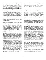
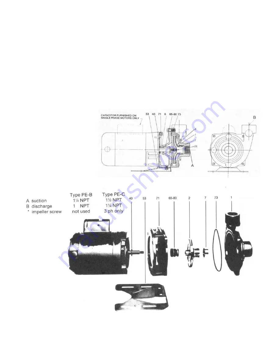
1 casing – cast iron
2 impeller – bronze
6 shaft – stainless steel
7 casing ring – bronze
*26 set screw – stainless steel
40 deflector – rubber
53 base – steel
71 adapter – cast iron
73 “o” ring seal
65-80 mechanical seal
2891096
filled. If debris is apt to be present, a combination foot-
valve strainer should be used. When the suction is under
pressure, or the level of the water is above the pump, a
valve and union should be installed in both the suction
and discharge pipes to permit inspection and service of
the pump at any time. To obtain optimum performance,
suction pipe joints must be made up with pipe joint
compound to insure that there are no air leaks. When
the pump is located above the liquid or operating with a
suction lift, even a small air leak in the suction line will
materially reduce capacity of the pump or cause a loss
of prime. If a union is required, use a gasket type and
seal it with pipe joint compound. Also, the pump must
not support heavy suction of discharge piping, and
piping must not be forced into place because this should
result in distortion and binding of rotating parts.
FIGURE 1. CLOSE COUPLED SERIES PE-B AND PE-C
3

