1-5.
CLEANING BEARINGS
a. Remove bearings from the housings, referring to dis-
assembly instructions.
b. Place bearings in a wire basket, so there is space
for the cleaning solvent to reach all parts.
c. Immerse the basket in Stoddard solvent or
equivalent, agitating the basket until grease is
thoroughly loosened and can be flushed out.
2-1.
INSPECTION.
Visually inspect parts for damage
affecting serviceability or sealing. Emphasize
inspection of mating parts having relative motion –
wear rings, for example. Perform detail inspection as
follows:
a. Check O-rings and bearing cover gaskets for
cracks, nicks or tears; packing rings for excessive
compression, fraying or shredding, embedded particles
(dirt or metal). Replace if defective in any way.
b. Mount the shaft between lathe centers. Check the
eccentricity trough out entire length with a dial indicator
to be not more than .003 inch total indicator reading.
Check that threads are clean and sharp. Surfaces on
which bearings mount must be smooth, have a finish
not less than 32 micro-inches, and have shoulders
square and free from nicks.
c. Measure the OD of the integral impeller wear
surfaces and the ID of the casing rings (7 and 7A).
Compute the diametrical clearance (ID minus OD) and
compare with the limit given in Figure No. 5. ID surface
of casing ring must be smooth and concentric. For
pumps equipped with impeller rings, clearances should
not exceed two times the maximum amount shown for
pump type in Figure No. 5.
d. Measure OD of inter stage sleeves (58, 58A)
(balancing disc (56) and ID of inter stage bushings
(113, 113A). Compute diametrical clearance and
compare with limits given in Figure No. 6. ID surface of
inter stage bushing must be smooth and concentric.
Sleeve lands must be free from burrs and flat spots.
e. Examine impeller passages for cracks, dents,
gouges or embedded material.
f. Check upper and lower casing machined surfaces to
be free of burrs or nicks.
g. Inspect shaft sleeves (14) for excessive wear.
h. Inspect bearings according to Table I.
FIGURE 5
2883819
d. Place bearing on a screened surface.
e. Using a spray gun with air filter and clean Stoddard
solvent, flush each bearing until all grease and sludge
is removed.
f. Blow solvent out of bearings with dry filtered air.
g. Lubricate bearings immediately after cleaning with
light spindle oil and place them in a covered container.
h. Do not spin bearings any time during cleaning.
2-2.
REPAIR.
Make needed repairs in the following
manner:
a. If ID of casing ring (7, 7A) is grooved, scored or
eccentric, bore to produce a smooth, concentric
surface, replacement of casing ring and impeller ring is
recommended. Measure and record the new ID.
b. If impeller rings are defective, or mating casing rings
require boring, remove old rings by turning in a lathe –
be sure machining is concentric with impeller ID. Use
care NOT to reduce hub OD.
NOTE
For bronze impellers and rings, the ring is shrunk on
the hub according to standard fit FN-4 or ANSI B4.1
standards. For pumps of 10-inch discharge and larger,
the rings are also tack welded to the hub at 3 places
120 degrees apart. Hardened impeller rings are
installed according to ANSI B4-1 standard fit FN-1.
c. Install new rings on the impeller (shrink or press
depending on material and tack weld if old rings were
tacked. This ID is factory – machined for proper fit.
d. Turn the OD of the new rings to provide the proper
diametrical clearance and to be smooth and concentric
with hub bore. Use clearance limit from Figure No. 5
and ID of casing ring from paragraph 2-2a. to compute
OD of impeller rings.
e. Replace worn shaft sleeves.
f. Straighten or replace shaft having excessive run-out
(eccentricity).
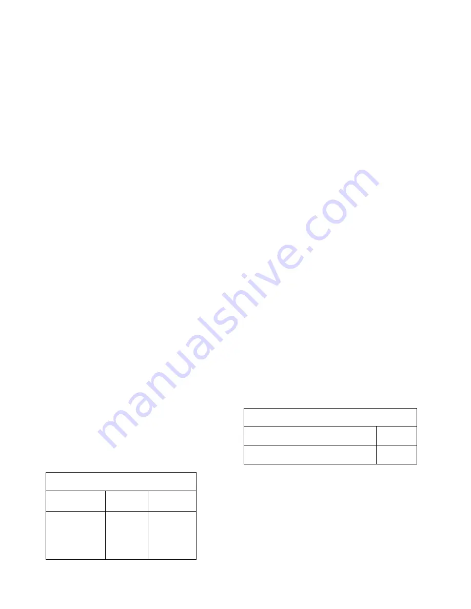
INTERSTAGE SLEEVE/BUSHING
DIAMETRICAL CLEARANCE (inches)
0.008
0.012
0.012
0.015
1-1/2TUT74,1-1/2TUT7G4, 2TUT8-4,
2TUT8A4, 3TUT9-4 ,3TUT9A4
2TUT9-5
2TUT9A5
FIGURE 6
NOTE
Clearances are for standard or cast iron fitted pumps.
For materials with a tendency to gall, such as stainless
steel, increase clearance approximately .010 inch.
IMPELLER/CASE WEAR RING
DIAMETRICAL CLEARANCE (inches)
0.010
0.014
0.012
0.016
0.023
0.027
1-1/2TUT74
1-1/2TUT7G4
2TUT8-4
2TUT8A4
3TUT9-4
3TUT9A4
4TUT10-4
4TUT10A4
4TUT10G4
2TUT9-5
2TUT9A5
SECTION II
INSPECTION AND REPAIR
8


