background image

ISSUED: 08-08-08  SHEET #: 055-9094-1

Visit the Peerless Web Site at www.peerlessmounts.com

For customer care call 1-800-865-2112 or 708-865-8870.

1 of 16

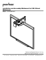
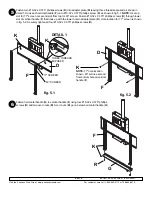
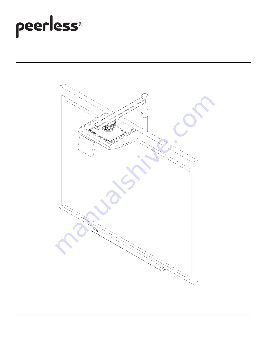
Installation and Assembly: Wallmount for CPA100 and

Whiteboard

Model:

 A100IWBMOUNT

3215 W. North Ave.  •  Melrose Park, IL 60160  •  (800) 865-2112 or (708) 865-8870  •  Fax: (708) 865-2941  •  www.peerlessmounts.com

Maximum Load Capacity for Screen: 

53 lb (24 kg)

Maximum Load Capacity for Projector :

 13.5 lb (6 kg)

Summary of Contents for A100IWBMOUNT

Page 1: ...865 2112 or 708 865 8870 1 of 16 Installation and Assembly Wallmount for CPA100 and Whiteboard Model A100IWBMOUNT 3215 W North Ave Melrose Park IL 60160 800 865 2112 or 708 865 8870 Fax 708 865 2941 w...

Page 2: ...nd position equipment Tighten screws firmly but do not overtighten Overtightening can damage the items greatly reducing their holding power Carriage box has over 100 lbs 43 kg of pressure Be careful n...

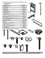
Page 3: ...x 12 mm serrated washer head socket pin screw 8 510 1050 M 0 25 ID spacer 4 590 1050 N 1 4 20 x 1 0 hex head screw 2 520 1606 O 10 32 x 3 8 serrated washer head socket pin screw 2 520 1151 P 0 25 ID n...

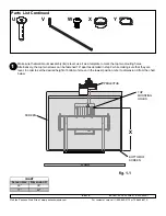
Page 4: ...template to mark the top two mouting holes Alternatively the top two screws can be fastened 16 apart as detailed in step 2 while making sure that they are level In order to set the desired height of b...

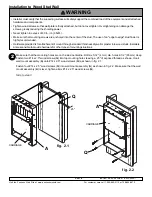
Page 5: ...5 wood screws Q Skip to step 3 Installation to Wood Stud Wall Installer must verify that the supporting surface will safely support the combined load of the equipment and all attached hardware and com...

Page 6: ...their holding power Never tighten in excess of 80 in lb 9 N M WARNING SOLID CONCRETE CINDERBLOCK Always attach concrete anchors directly to load bearing concrete Never attach concrete anchors to conc...

Page 7: ...read on each as shown in fig 2 4 Hook wall mount assembly A onto 1 4 20 x 2 1 2 screws Fasten four 1 4 20 x 2 1 2 screws into wall mount assembly A as shown in fig 2 5 Make sure that the wall mount as...

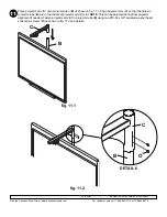
Page 8: ...s K Slide projector tube B into top of wall mount assembly A and secure with two 10 32 x 0 375 phillips screws K as shown below NOTE Use correct set of mounting holes for the screen size as shown belo...

Page 9: ...from top for 63 screen Fasten 10 32 x 0 375 phillips screws K through lower slot of vertical handle F that lines up with the lower hole in adapter plate D Hole location for 77 screen is shown in fig 5...

Page 10: ...800 865 2112 or 708 865 8870 10 of 16 Insert hook brackets into screen as shown in detail 2 and fig 7 1 Secure each hook bracket E with M6 x 12 mm serrated washer head socket pin screw L as shown in...

Page 11: ...h hook bracket E using security allen wrench V and tighten to wall plate as shown in detail 5 To remove screen from mount loosen safety security screws and lift screen off of mount Do not tighten scre...

Page 12: ...ws N four 0 25 ID nylon washers P and slide plate I as shown in fig 10 2 and 10 3 Do not tighten 1 4 20 x 1 0 hex head screws N fully to allow for adjustment Insert rectangle plug S into projector arm...

Page 13: ...tor tube B as shown in fig 11 1 Align projector arm C so that the holes in projector tube B are in the middle of projector arm C slot NOTE This can be adjusted during final projector alignment if need...

Page 14: ...on block indi cates the back of projector The screws L should be placed in the center of slots This can be adjusted during final projector alignment if needed SHOULDER CONNECTION BLOCK CONNECTION BLOC...

Page 15: ...J IMPORTANT For security installations insert one 10 32 x 1 4 socket pin screw W through projector mount assembly J and into connection block as shown Tighten screw using 4mm security allen wrench V C...

Page 16: ...OR YAW SWIVEL STOP KNOBFORROLL ADJUSTMENT KNOBFORPITCH ADJUSTMENT BACKOFMOUNT To prevent tampering with the pitch and roll adjustments Tighten the two tamper resistant security screws on the projector...

Reviews: