background image

Visit the Peerless Web Site at www.peerlessmounts.com

ISSUED: 03-26-09  SHEET #: 125-9060-5   07-26-13

Max Load Capacity:125 lb (56.6 kg)

Installation and Assembly:

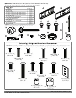
SLIDE OUT WALL MOUNT

Models:


DMU50SM

Summary of Contents for DMU50SM

Page 1: ...Visit the Peerless Web Site at www peerlessmounts com ISSUED 03 26 09 SHEET 125 9060 5 07 26 13 Max Load Capacity 125 lb 56 6 kg Installation and Assembly SLIDE OUT WALL MOUNT Models DMU50SM...

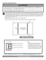
Page 2: ...9413 M 3 4 EMT nut 1 560 0049 N lock and key not shown 1 560 0755 O concrete anchor 4 590 0320 Parts List Before you start check the parts list to insure all of the parts shown are included IMPORTANT...

Page 3: ...ghten wood screws so that wall plate is firmly attached but do not overtighten Overtightening can damage the screws greatly reducing their holding power Never tighten in excess of 80 in lb 9 N M Make...

Page 4: ...r mounting holes Drill four 1 4 6 mm dia holes to a minimum depth of 2 5 64 mm Insert anchors O in holes flush with wall as shown right Place wall plate over anchors and secure with 14 x 2 5 screws I...

Page 5: ...nts com ISSUED 03 26 09 SHEET 125 9060 5 07 26 13 Note Lock will NOT function properly if lock parts are in wrong position Secure lock N into wall plate A by using parts provided with lock and 3 4 EMT...

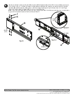
Page 6: ...Notes The number of fasteners used will vary depending upon the type of screen Multi washers and spacers may not be used depending upon the type of screen Use the corresponding hole in the multi wash...

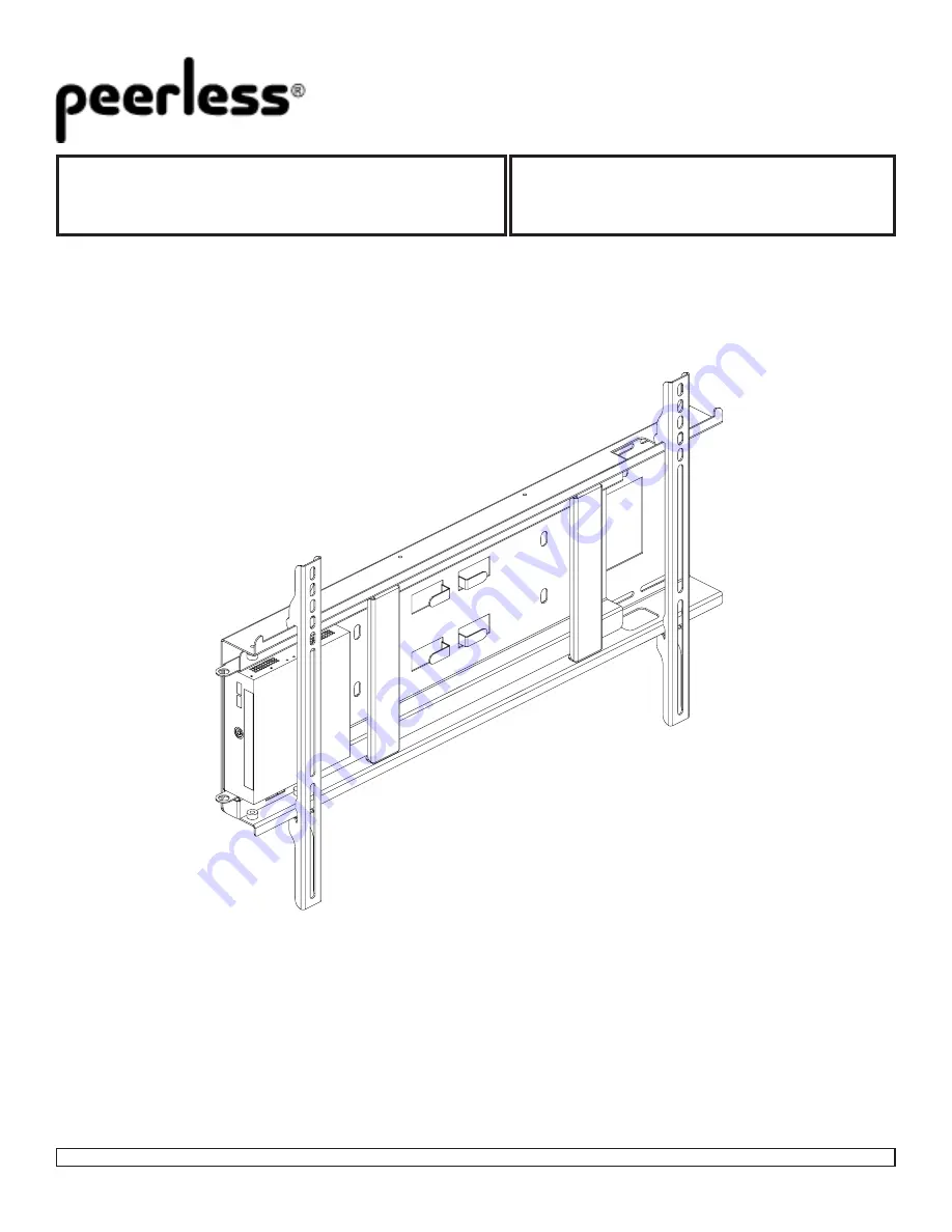
Page 7: ...Refer to Screen Compatibility Chart to determine the proper fastener to use Visit www peerlessmounts com 2 for a full screen compatibility chart for this mount Begin with longer length screw hand thr...

Page 8: ...Screen can be adjusted horizontally if desired NOTE To lock the screen down fully tighten M5 x 25 mm socket pin serrated washer head screws F to wall plate as shown in cross section To remove screen f...

Page 9: ...ed by flange in top as shown in fig 6 2 Use finger holes when sliding slide out bracket B in and out of wall plate A 6 fig 6 1 fig 6 2 MEDIA BOX B J K A B SPACERS FLANGE Detail 1 FINGER HOLES Note onc...

Reviews: