background image

4 of 9

ISSUED: 03-02-11   SHEET #: 125-9192-1

B

I

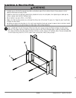
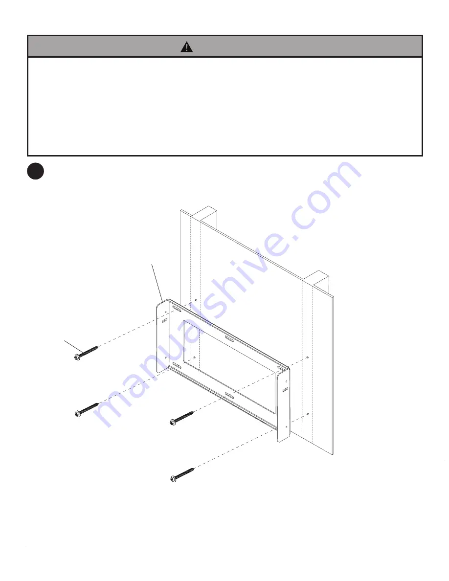
Installation to Wood Stud Walls

Use a stud finder to locate the edges of the stud. Use of an edge-to-edge stud finder is highly recommended. 

Based on its edges, draw a vertical line down the stud's center. Place wall plate (

B

) on wall as a template. Mark 

the center of the four mounting holes. Drill four 5/32" (4 mm) dia. holes 2-1/2" (65 mm) deep. Secure wall plate (

B

to wood stud using four #14 x 2-1/2" wood screws (

I

) as shown. Skip to Step 2 page 7

•  Installer must verify that the supporting surface will safely support the combined load of the equipment and all 

attached hardware and components.

•  Tighten wood screws so that wall plate is firmly attached, but do not overtighten. Overtightening can damage the 

screws, greatly reducing their holding power.

•  Never tighten in excess of 80 in. • lb (9 N.M.).
•  Make sure that mounting screws are anchored into the center of the stud. The use of an "edge to edge" stud finder 

is highly recommended.

•  Hardware provided is for attachment of mount through standard thickness drywall or plaster into wood studs. Install-

ers are responsible to provide hardware for other types of mounting situations.

WARNING

1

Summary of Contents for HT642-002

Page 1: ...Model HT642 002 Installation and Assembly Wall Mount Max Load Capacity 75 lb 34 kg ISSUED 03 02 11 SHEET 125 9192 1...

Page 2: ...the combined load of the equipment and all attached hard ware and components Never exceed the Maximum Load Capacity of 75 lb 34 kg If mounting to wood wall studs make sure that mounting screws are anc...

Page 3: ...et 1 201 1881 B wall plate 1 201 1678 C 8 washer 4 540 1001 D M4 x 12 mm phillips screw 4 504 9013 E M6 x 16 mm phillips screw 4 520 9274 F 4 mm allen wrench 1 560 9646 G toggler 4 560 9708 H 1 4 20 p...

Page 4: ...nstaller must verify that the supporting surface will safely support the combined load of the equipment and all attached hardware and components Tighten wood screws so that wall plate is firmly attach...

Page 5: ...all and studs at lo cations corresponding to wall plate Insert togglers G as shown below Skip to Step 2 page 7 G Align wall plate with hole in wall and fasten using 1 4 20 x 2 5 screw H wall plate H P...

Page 6: ...that you have a minimum of 1 3 8 of actual concrete thickness in the hole to be used for the concrete anchors Do not drill into mortar joints Be sure to mount in a solid part of the block generally 1...

Page 7: ...rews D 8 washers C are required NOTE Adapter brackets L have 2 of vertical adjustment as shown in detail 1 200 mm 100 mm BOTTOM OF DISPLAY 200 mm x 100 mm HOLE PATTERN SHOWN ABOVE 400 mm 200 mm 2 OF V...

Page 8: ...ttach two M5 x 12 mm serrated washer head socket pin screws J through the slots on the sides of wall plate B and threaded holes of adapter plate A Tighten with the 4 mm security allen wrench F Attach...

Page 9: ...A SLOT B Attaching Mounting Bracket Using Tilt Option To secure wall plate B to adapter plate A adjust tilt as desired and attach two M5 x 12 mm serrated washer head socket pin screws J into the slots...

Reviews: